82
S
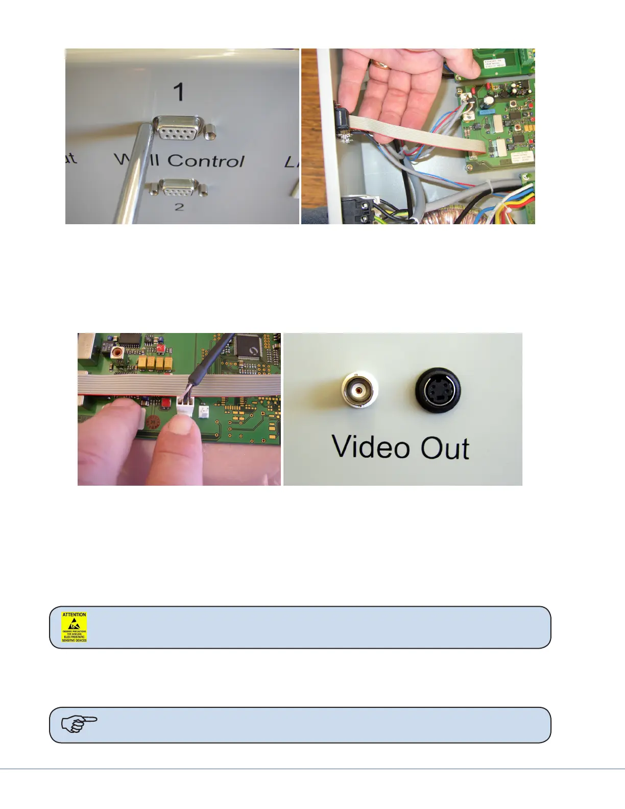
5. Connect the female DB-9 connector removed from the power supply box to the male DB-9 con-
nector on the Camera Control and Video board.
6. Mount the female DB-9 connector on the end of the ribbon cable from the Camera Control and
Video board to the power supply box front panel.
7. Remove the video cables from the Camera Control board to allow them to be fed through the
front of the power supply box. Use your nger to release the clip on the connectors.
8. Route the Video cables through the front of the power supply box. Mount them with supplied
hardware.
9. Reconnect the video cables internally to the Camera Control and Video board.
10. Reinstall the cover on the power supply box.
11. Connect the power cable to the power supply box.
13.1.5 Camera Installation
Caution Follow ESD prevention procedures.
12. Remove the original light handle assembly.
13. Put two new light bulbs into the light bulb section of the in-light camera. Ensure they are prop-
erly seated and not tilted.
Note Do not touch the light bulbs directly with your ngers. is will shorten bulb life.