130
S
3. read two M6x25 screws through the bottom plate (Item 9) into the extrusion and tighten.
4. Retighten the M6x25 screws on the opposite extrusion.
5. With a Phillips screwdriver, tighten the M5x25 screws attaching the side modules to the service
head. Note that there are two screws per module, per extrusion. (Item 3) Repeat for all remain-
ing screws.
6. Re-attach all UL brackets (one screw each).
7. Insert Vertical Separators into groove of extrusion on the opposite side and replace the two
screws in each.
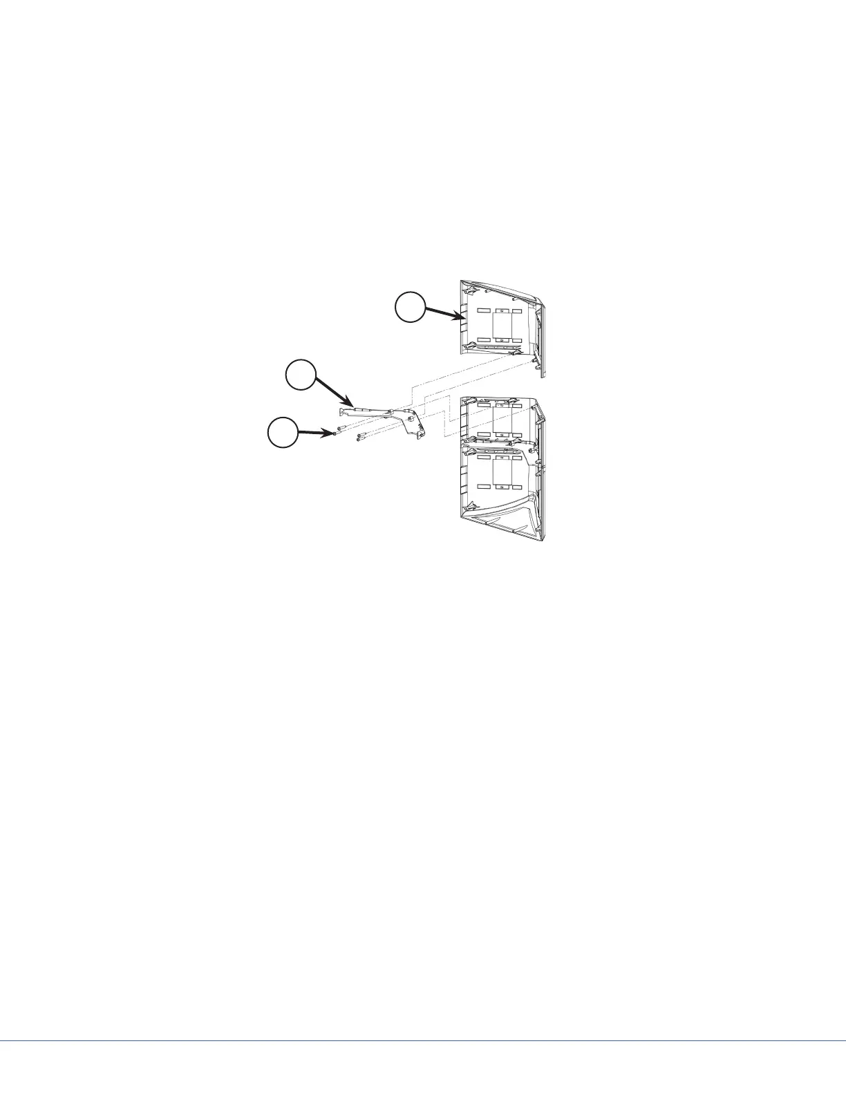
17.7.5 Removing Modules
3
2
1
End Module
1. Using a Phillips screw driver, remove any vertical separators or UL brackets from the extrusions
(see Section 17.5.3 - Removing Extrusions).
2. Remove the four M5x25 screws on both sides of the module attaching it to the extrusions.
3. Remove the two M4x16 and M4x25 screws attaching the horizontal separator to the side mod-
ule (Item 1 in the gure above).
4. Remove any latch valves or electrical outlets from the module.
5. Tilt the open end away from the service head to release the set pins (Figure X, #4) and pull the
module away, as shown in the following gure.