131
S
Side module
1. Loosen either one of the end modules.
2. Remove any vertical separators or UL brackets from the extrusions (see Section 17.5.3 - Remov-
ing Extrusions).
3. Remove the M5x25 screws and on either side of the module attaching it to the extrusions.
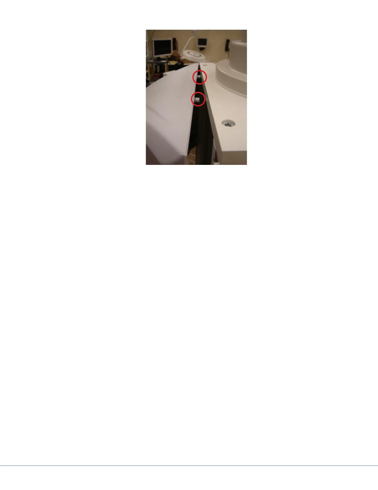
4. Remove four M4x16 and M5x25 screws attaching the horizontal separators to the side module
(Item 1 in the gure above); there are two screws attached to each horizontal separator.
5. Remove any latch valves or electrical outlets from the module.
6. e side module will be tucked into each separator, so carefully extract the side module from
the separator and then from the service head.