132
S
17.7.6 Installing Modules
WARNING Power should be cut from the boom system prior to removing any mod-
ules.
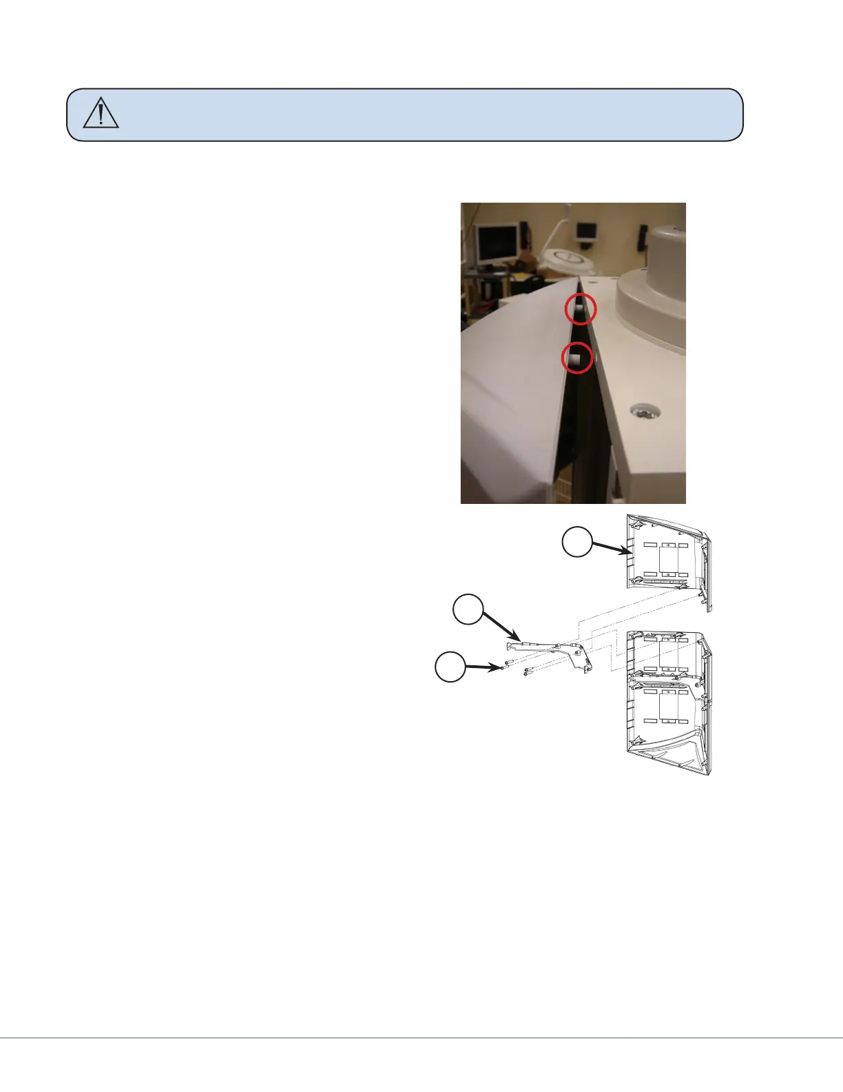
End Module
1. Fit the end module into the horizontal
separator groove and then insert the set
pins into the top/bottom plate.
2. Reconnect and reattach any latch valve as-
semblies or power outlets.
3. Attach two M4x16 and M5x25 screws with
a Phillips screw driver through the hori-
zontal separator to the side module (Item
1 below)
4. Attach the two sets of four M5x25 screws
on either side of the module, attaching it to
the extrusions.
5. Reconnect and reattach any latch valve
assemblies or power outlets, or other low
voltage plates..
6. Reinstall any vertical separators or UL
brackets into the extrusions (mentioned in
Section 17.5.3, Removing Extrusions).
3
2
1
Side module
1. With either end module loosely tted, insert the side module into both horizontal separators.
2. Reconnect and reattach any latch valve assemblies or power outlets.
3. Using a Philips screwdriver, attach the four M4x16 and 5x25 screws through the horizontal
separators to the side module (Item 1 in the preceding gure); there are two screws attached to
each horizontal separator.
4. Attach both sets of four M5x25 screws on either side of the module attaching it to the extru-
sions.
5. Reconnect and reattach any latch valve assemblies, power outlets, or other low voltage plates.
6. Reconnect and reattach any latch valve assemblies or power outlets.