103
S
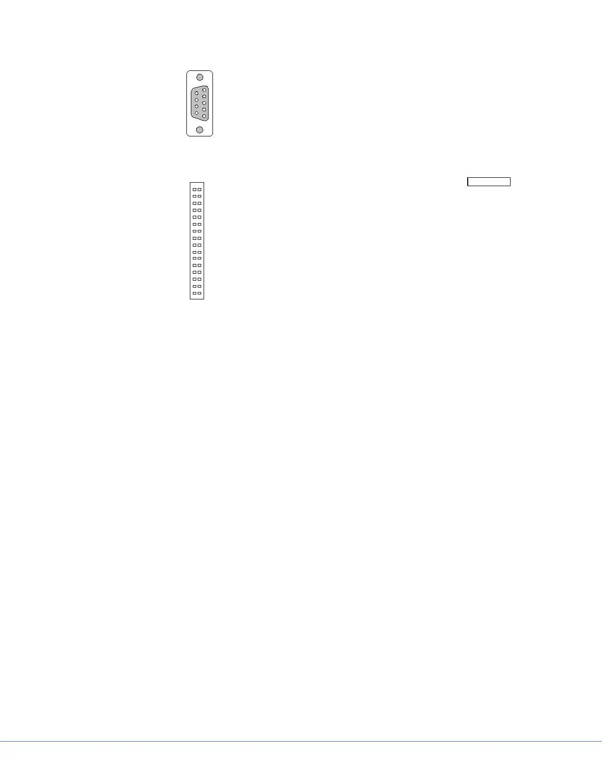
16.5.2 Plug Allocation Operating Console and Diagnostic LEDs
SUB-D
9-pole
male
2- row male
multipoint
connector for
connection of
light and
camera
12
Camera
Pin2: Inlet Trace 7..17 (GND)
Pin4: Common for LED17..19
Pin6: Cathode LED19
Pin8: Cathode LED18
Pin10: Cathode LED17
Pin12: Feedback Trace 13
Pin14: Feedback Trace10
Pin16: Feedback Trace 9
Pin18: Feedback Trace 8
Pin20: Feedback Trace12
Pin22: Feedback Trace 11
Pin24: Feedback Trace 7
Pin26: Feedback Trace 15
Pin28: Feedback Trace 16
Pin30: Feedback Trace 14
Pin32: VCC (not connected)
Light 2
Pin1: GND for Trace 4..6
Pin3: VCC LED9..16
Pin5: VCC LED9..16
Pin7: Cathode LED9
Pin9: Cathode LED16
Pin11: Cathode LED15
Pin13: Cathode LED14
Pin15: Cathode LED13
Pin17: Cathode LED12
Pin19: Cathode LED11
Pin21: Cathode LED10
Pin23: Feedback Trace6
Pin25: Feedback Trace5
Pin27: Feedback Trace4
Pin29: Feedback Trace (Reserve)
Pin31: Feedback Trace (Reserve)
Light 1
Pin1: GND Trace 1..3
Pin3: VCC LED1..8
Pin5: VCC LED1..8
Pin7: Cathode LED1
Pin9: Cathode LED8
Pin11: Cathode LED7
Pin13: Cathode LED6
Pin15: Cathode LED5
Pin17: Cathode LED4
Pin19: Cathode LED3
Pin21: Cathode LED2
Pin23: Feedback Trace3
Pin25: Feedback Trace2
Pin27: Feedback Trace1
Pin29: Feedback Trace (Reserve)
Pin31: Feedback Trace (Reserve)
Without Camera!
1
Pin 1: + 24V)
Pin 2: RxD
Pin 3: TxD
Pin 4: Not Connected
Pin 5: GND (System)
Pin 6: + 24V)
Pin 7: CAN low
Pin 8: CAN high
Pin 9: GND (System)
Case: Sheild CAN-Bus
LED1: blinks rapidly (visible blinking): Micro-controller is in main routine.
LED2: blinks with approx. 1 Hz: CAN communication with electric control system is OK.
blinks with approx. 3 Hz: CAN communication with electronic control system is not OK (will
only by analyzed after Power Up).
LED1
Blinks rapidly (visible blinking): Micro-controller is in main routine.
LED2
Blinks with approx. 1 Hz: CAN communication with electronic control system is OK. Blinks with ap-
prox. 3 Hz: CAN communication with electronic control system is not OK (will only be analyzed aer
Power Up).
16.5.3 Plug Locations of the Power Box
e positions of the plug-in connections of the power box are described below.
Upper row, No. 1 connects light system 1, which is the upper light on the support arm. e lower row,
No. 2 connects the lower system to the support arm accordingly.