67
S
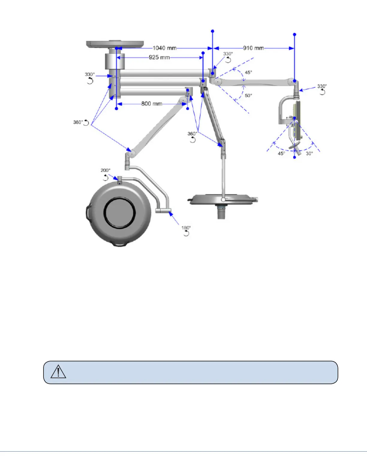
Light Suspension Adjustment Points
11.4 Boom Arms
11.4.1 OSC400
11.4.1.1 Mounting Flange
1. Loosen the six set screws (3) in each stop ring (2).
2. Rotate the stop ring (2) to the desired position relative to the xed stop (1).
3. Tighten the six set screws (3) in each stop ring per stop (2).
4. Ensure that stop rings are in desired position and securely fastened by moving the boom
WARNING To prevent the internal supply lines from being twisted o, at least one
stop ring (2) must be locked.
11.4.1.2 Tandem (Long-Flange) Booms
1. To set the stops at the lower ange, the cover (5) must be removed.
2. Remove the three (M3 X 6mm) screws (4) and slide the cover (5) down.
3. Set the stops as described above for the Single (Regular-Flange).
4. Slide the cover (5) up and replace and tighten the three retaining screws (4).