45
S
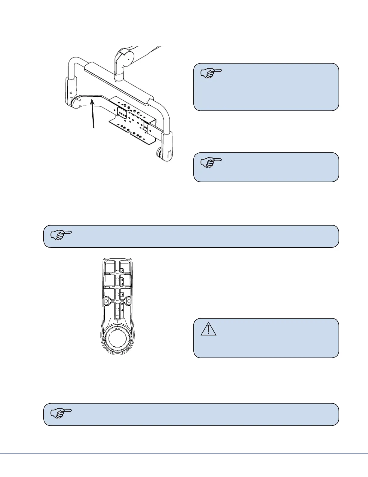
10.2.2 Adjusting the Height
Left Cable Cover
Le cable cover
1. Remove the cable cover from the le Pivot
Arm where the cables are concealed.
Note It is not necessary to remove
the cable cover from both
horizontal arm supports,
only the le side where the
cables are concealed.
2. Remove the M5 screws from either the le
or right Height Adjust Clamp. Use care
when removing the screws, as pieces of the
clamp may fall o.
Note For ease of installation,
adjust the height one arm at
a time.
3. Remove the outer piece of the Height Adjust Clamp and remove the tube alignment pin from
the inner piece.
4. Use Table 10.1 to determine the appropriate hole to seat the alignment pin into in the inner
piece of the Height Adjust Clamp.
Note Measurements presented in the table are estimates only. Adjustments may need
to be made before completing installation to ensure correct balance and t.
Height Adjust Clamp
5. Set the alignment pins in their respective
bracket holes in the inner Height Adjust
Clamp.
6. Reattach the outer Height Adjust Clamp
and secure with M5 socket head screws.
Tighten all screws to 35 lb. in. (3.95 Nm)
torque.
WARNING Ensure that all screws
are present. Missing
screws could result in
the yoke falling.
7. Repeat steps 1-5 for the opposite Height
Adjust Clamp.
8. Attach the cable cover to the Le Pivot Arm, using three M4 X 12 button head socket cap
screws. Hand tighten all screws fully.
Note Ensure that cables do not get pinched.