99
S
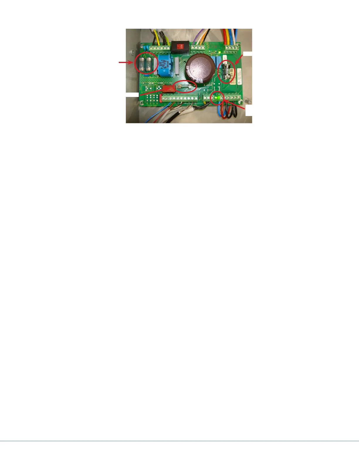
2A Fuse
4A Fuse
10A Fuse
“Light Power”
LED
Power Supply Board Fuses and LEDs
l. Turn power supply box power switch to the OFF position.
m. Remove and discard the old 4A fuses on the power supply box motherboard and replace with
new 4A fuses.
n. Remove and discard the 2A fuse on the power supply box motherboard and replace with new
2A fuses.
o. Turn power supply box switch to the ON position.
p. Do both lights work? If yes, then replace the power supply box cover, check the system for
normal operation, as per QIP07056. If no, replace the power supply box cover, remove the
power supply box and return it to Stryker Communications using the RMA process. In-
stall a replacement power supply box and test the light system for normal operation, as per
QIP07056.
16.3 Wall Control
e wall control consists of a front panel with LED display and keys for user input. e electronic cir-
cuit with a micro-controller is located behind the front panel. It is responsible for processing the user
input for camera and light controls and for output certain operating conditions on the LEDs. Commu-
nication with the primary electronic control system takes place via the CAN bus. e electronic con-
trol system of the terminal has a 9-pole sub-D plug. All control signals (CAN, serial) and the voltage
supply utilize this plug. e circuits are connected separately to comply with EMC regulations.
e terminal has two equivalent electronic control systems, because every light system consists of two
independent lights.
e functions of the terminal are briey described in the following diagram.