98
S
WARNING To avoid risk of electrical shock, all service must be provided by authorized
personnel.
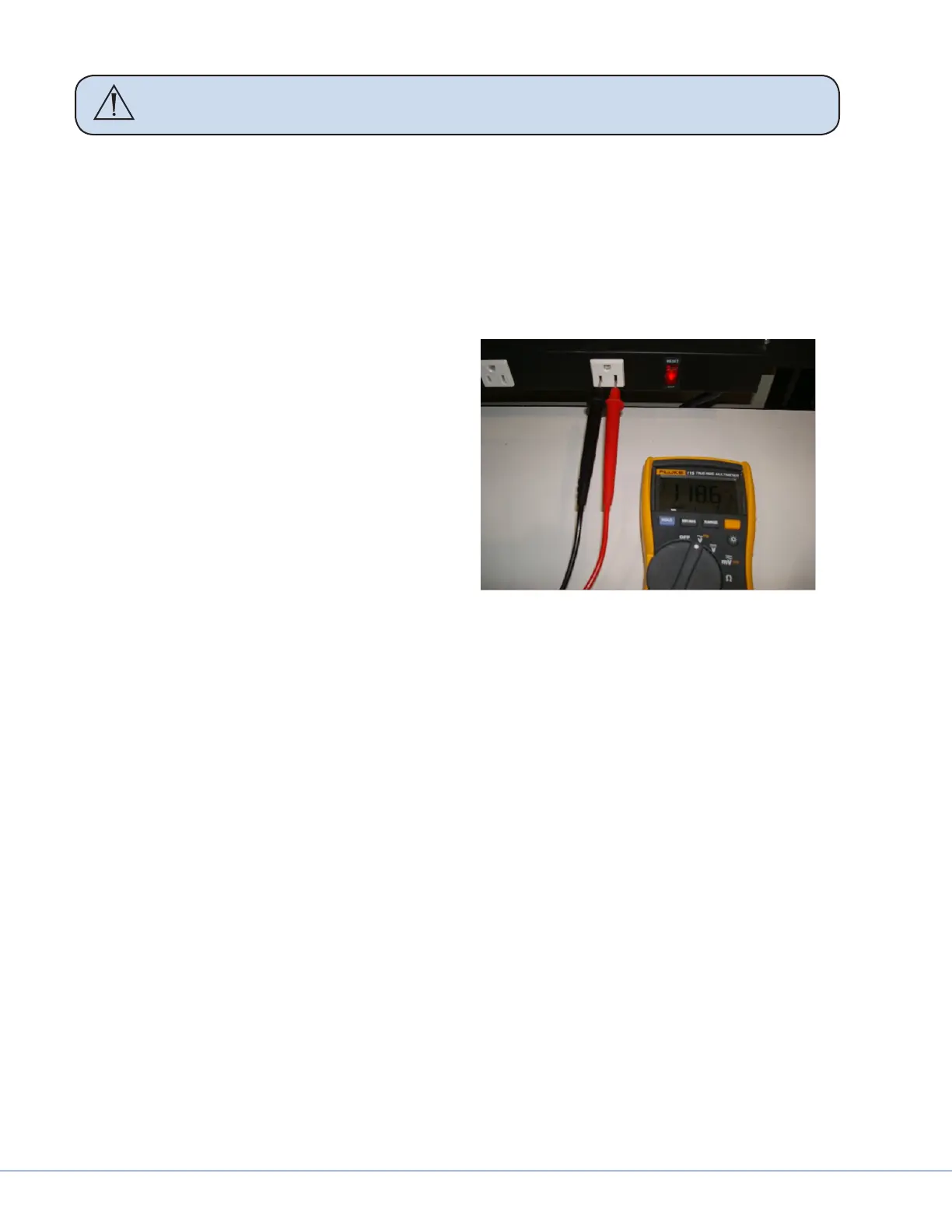
c. Set multimeter to VDC mode.
d. Insert multimeter leads as shown in the previous gure.
e. Voltage output should be 33VDC+/- 1VDC.
f. If the light that is not working has 33VDC power, the power supply is not the cause of the
problem. Continue troubleshooting the rest of the light system.
g. If the aected light does not have 22VDC power out, go to the next step.
7. Troubleshoot internal power supply components.
a. Turn the power supply box power
switch to the OFF position.
b. Remove the top cover from the power
supply box by removing the four Phil-
lips screws from the sides.
c. Inspect the inside of the power supply
box for obvious damage to the internal
components such as physical damage to
circuit boards or electrical components,
damaged/loose wiring, and blown fuses.
d. Turn the power supply box power
switch to the ON position.
Line Voltage Measurement
e. Check if the “LIGHT POWER” LED is illuminated for the aected light as shown in the gure
below.
f. Using a non-conductive tool, tap the 10A fuse on the power supply box while watching the
“LIGHT POWER” LED. Check to see if the “LIGHT POWER” LED ickers when tapped (this
can indicate a cold-solder failure on this component).
g. Turn o power to the power supply box.
h. Remove the 10A fuse and discard it.
i. Install a new 10A fuse.
j. Turn the power supply box power switch to the ON position.
k. Does aected light turn on? If yes, then replace the cover on power supply box and test the
light system for normal operation, as per QIP07056. If no, proceed to the next step.