81
S
Note Do not place the cover on the light head until the entire procedure is complete
and the camera has been tested and aligned.
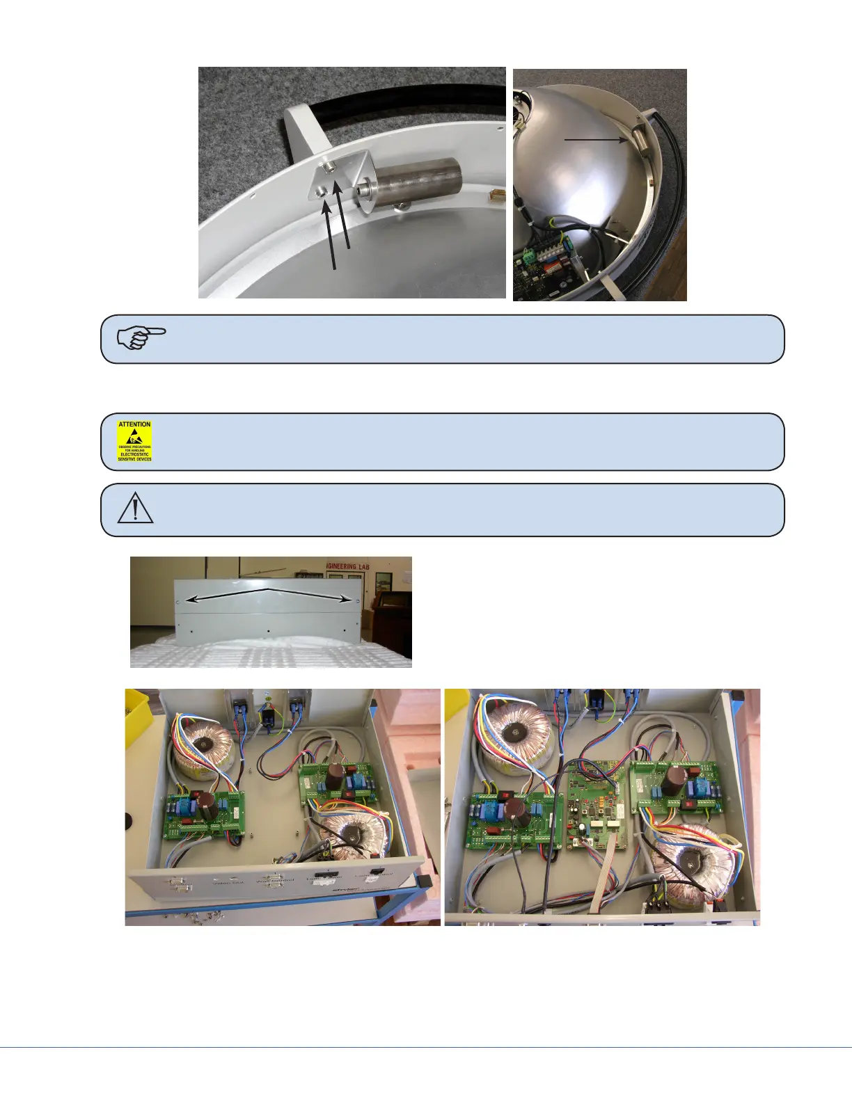
13.1.4 Power Supply Box Components
Caution Follow ESD prevention procedures.
Warning Ensure the power supply box is not connected to a power source prior to
proceeding with the following instructions.
1. Remove the cover to the power supply box
(power supply box) by removing the four
screws securing the top.
2. Locate the circuit board mount location
between the two power supply circuit
boards.
Without Circuit Board With Circuit Board
3. Mount the Camera Control and Video board in the power supply box using supplied hardware.
4. Remove the DB-9 connector from “Wall Control 1” position on the front of the power supply
box.