80
S
1. Remove the cover from the light head
by removing the 10 Phillips head screws
around the circumference of the light
head.
2. Gently li the light head cover from the
Light.
3. Locate the Light Circuit Board and the
Mount for the Image Data Transmitter
board.
4. Place the Image Data Transmitter board
near its mounting location but do not
fasten yet.
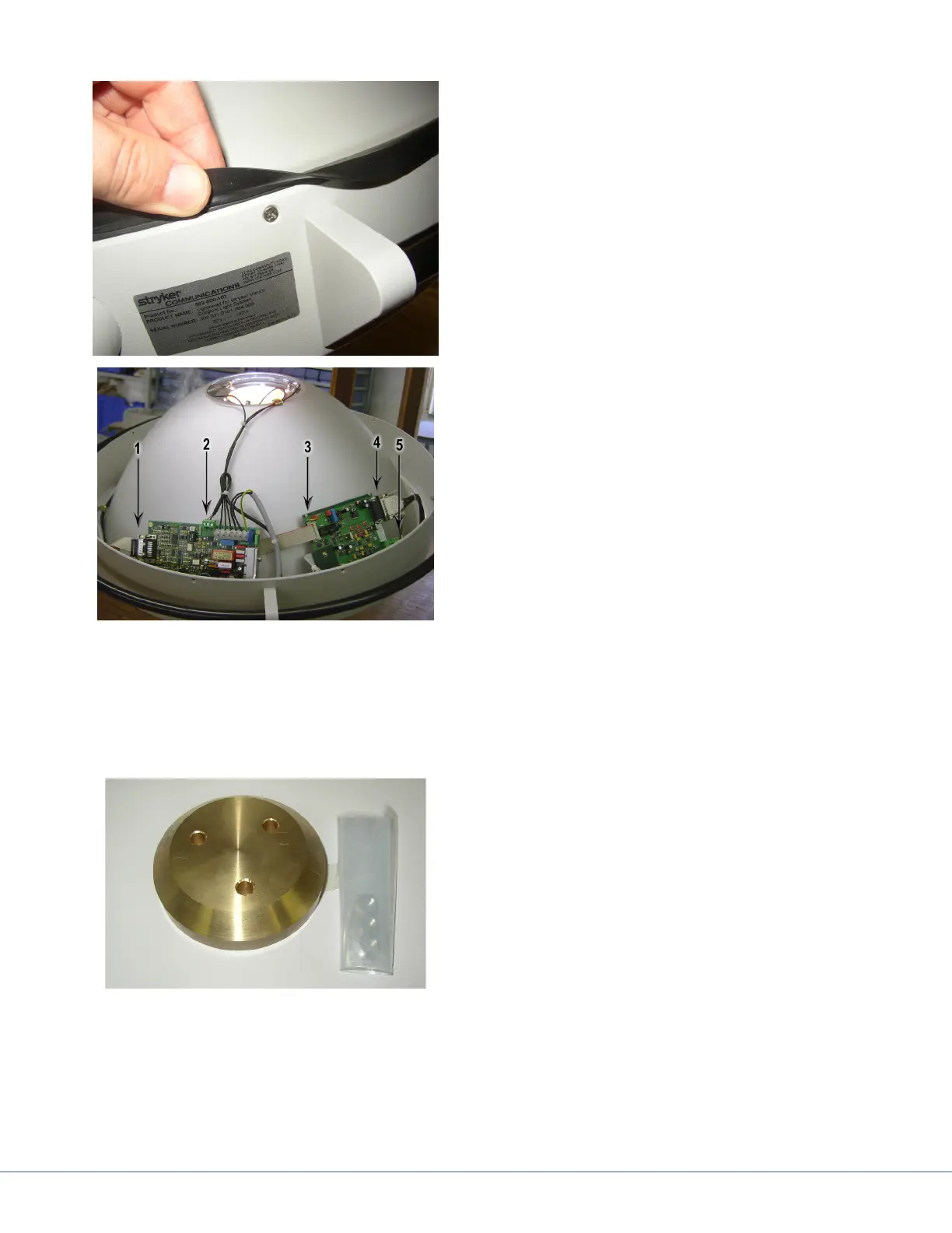
5. Using the photo to the le, connect all of
the electrical connectors.
6. Remove the original DB-15 connector
from location 1.
a. Connect it to location 4 on the Image
Data Transmitter board.
b. Remove the CAN Bus connector from
point 2 and connect it to location 5 on
the Image Data Transmitter board.
c. Connect the ribbon cable from the Image Data Transmitter board shown in location 3 and
dress it out behind the light circuit board and connect to location 1.
d. Connect the CAN Bus connector from the Image Data Transmitter to the original light board
in location 2. Dress the wiring using tie wraps as necessary.
e. Using the supplied mounting hardware fasten the Image Data Transmitter board to the
mounts.
7. Mount the camera counter weight to the
light head cover using supplied hardware.
e second counter weight mounts inside
the light head using existing hardware that
holds the hand rail onto the light head. If
this weight is present, remove it.
8. Loosen both screws.
9. Remove bottom screws completely and
swing the weight out of the way of the bot-
tom screw hole.
10. Re-insert the bottom screw and tighten.
11. Remove the top screw and weight.
12. Replace top screw.