18
S
5. Preparing the Mounting (Interface) Plate
Remove the hardware bag from the suspension box.
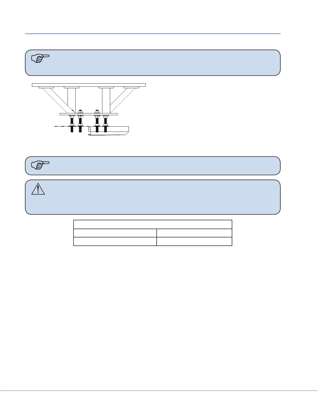
Note Ensure all-thread rods do not interfere with the application of ceiling cover by
performing a dry t. e all-thread rods should not extend below the base of the
cover. If they do, cut the rods back.
1. Install six hex nuts below Mounting (Inter-
face) Plate to align ange top approximate-
ly even with the bottom of nished ceiling.
2. Use a Torpedo Level to verify that the nuts
are level. Measure two sets at a time.
3. Place at washers and Plastic Isolation Discs (required in Europe) below each hex nut to hold in
place.
Note Plastic Isolation Discs are only required in Europe.
Caution No more than 8 inches of exposed all-thread rod is allowed between the Pre-
installation Plate and the down tube ange for Seismic considerations. No
more than 2 inches of exposed all-thread rod is allowed for Zone 4 installa-
tions.
Cover Size
180 mm (7 inches) 153 mm (6 inches)
80 mm (3 inches) 64 mm (2.5 inches)