33
S
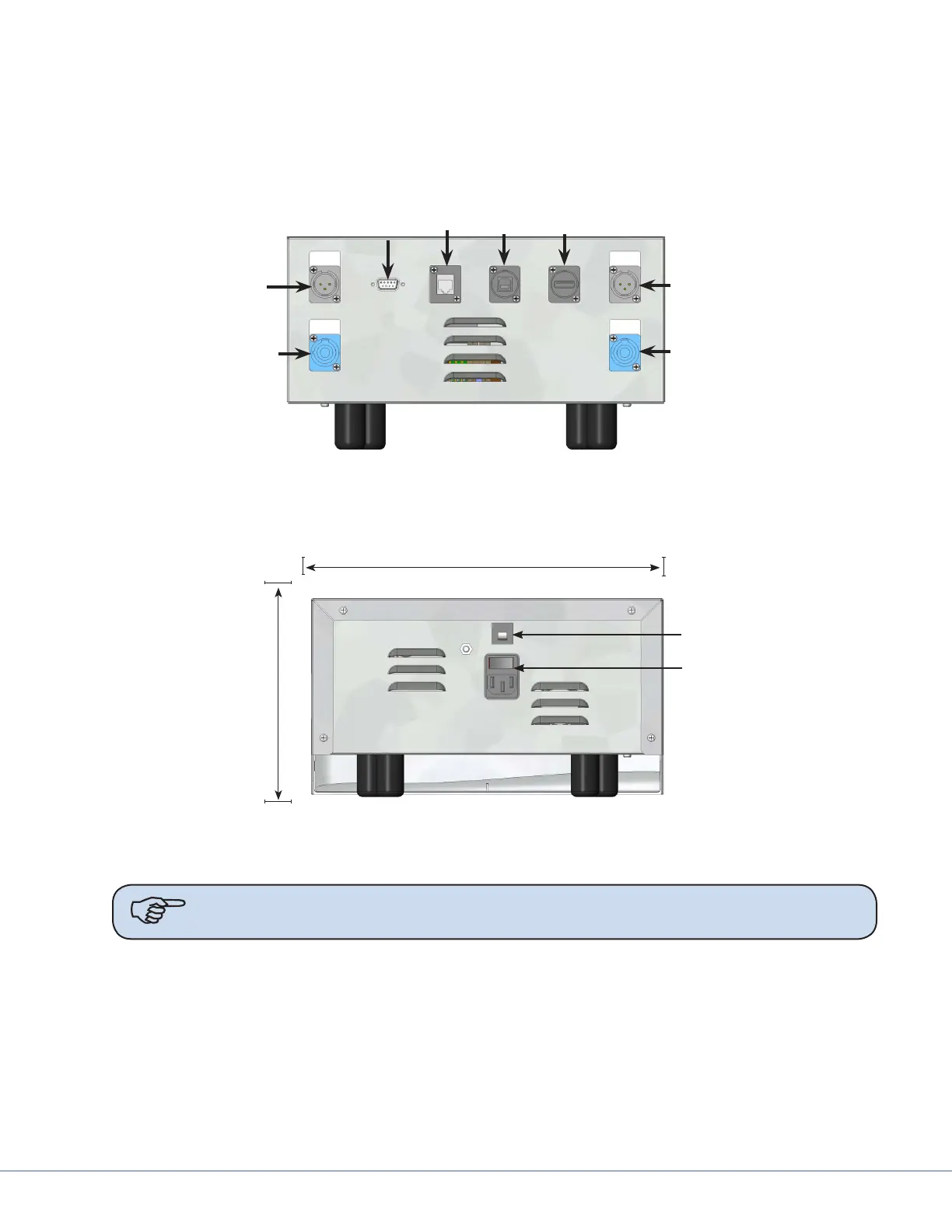
9.3 Power Supply Box Connections
Place the power supply box in the designated location in the documentation station.
e front of the power supply box has RS-232 and low voltage connections. e power inlet connector
is located on the rear side of the power supply box for the 115/230VAC power cord.
Wall
Connection
Port
Expansion
Port
Light Control
Light Power
Light Control
Light Power
SORN
Port
SIDNE
Port
Power Supply Box, Front View
Circuit Breaker
Power Inlet
12.5
(317.5)
7.0
(177.8)
Depth 15.5 (393.7)
INCHES (mm)
Power Supply Box, Rear View
Note Avoid blocking the fan exhausts or placing objects within 2 inches of the fan
exhausts.
To control the Visum LED Surgical Light and StrykeCam 2 In-Light Camera from the wall-mounted
control panel, the Light Power Connector and Wall Control Connector must be connected to a power
supply box. Review the sets of instructions and diagrams below for connections.