32
S
8. Verify all electrical connections are made, then have contractor turn breaker back on. Power up
the lights using the wall box.
9. Run lights through control, checking the following order:
a. On/o (10 times each light head).
b. Intensity up and down through the full range (10 times per light head).
c. Verify reserve bulb indicator is operational by removing the primary bulb from each light
head. e reserve bulb indicator on the wall control panel should light up. Replace primary
bulb aer turning o the lights.
Caution DO NOT touch the bulb directly with your hands.
9.2 LED Lights
9.2.1 Power Supply Box Wall Mount (Optional)
e power supply box wall mount should be used to securely install and mount a Visum LED power
supply box to a wall.
Mount a standard Hubbell Wiegmann (P/N SC101004) junction box to a wall and then install the
power supply box.
Note Consult the hospital to determine ideal placement for a power supply box before
mounting the junction box.
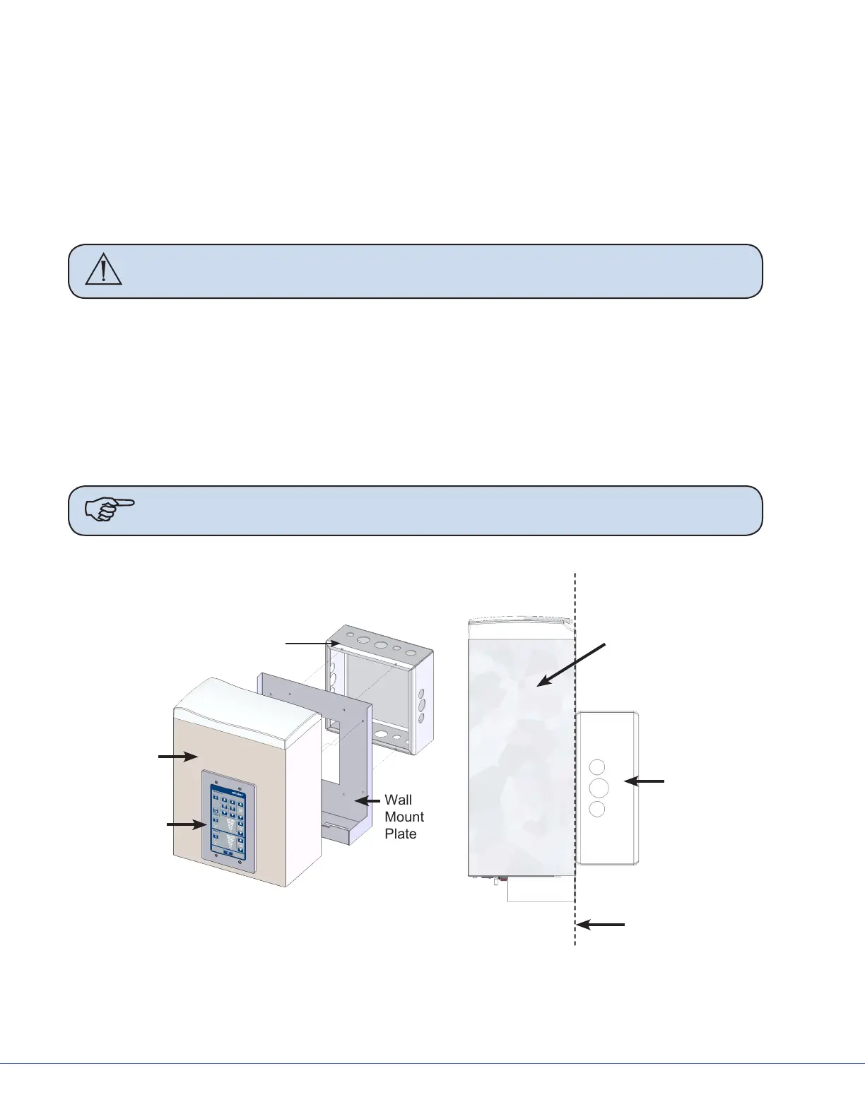
Exploded View of
Power Supply Box
Wall
Mount
Plate
Customer Supplied
Back Box*
Power
Supply Box
Control
Panel
Power Supply Box
Customer
Supplied
Back Box*
Wall
Vertical Side View of
Power Supply Box
and Back Box
*The Back Box is recessed ush within the wall.
Exploded/Side view of Power Supply Box