70
S
Note e two preinstalled stop screws (1) limit the lower extension arm swiveling
range to approximately 180 degrees.
1. Remove the stop screw (1).
2. Install the stop screw (1) in the desired threaded hole (2) relative to the xed stop (3) and
tighten it.
3. Move or remove second stop screw if necessary.
4. Ensure that stop screws are in desired position and securely fastened by moving the boom
Caution To prevent the internal supply lines from being twisted o, at least one
stop screw (1) must be installed.
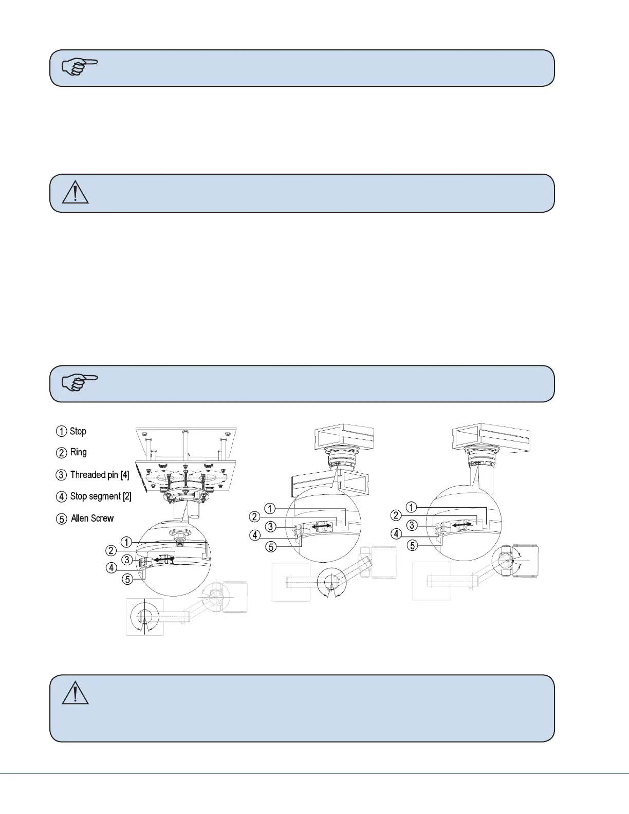
11.4.2 OSC600
1. Loosen the socket-head screws (5) and four threaded pins (3) in the mounting ange mechani-
cal stops.
2. Slide mechanical stops (4) on ring (2) to the desired position and tighten socket-head screws (5)
and four threaded pins (3).
3. Ensure mechanical stops are seated securely.
4. Repeat for mechanical stops in middle bearing (if available).
5. Repeat for mechanical stops in service head bearing.
Note Adjust pneumatic brakes prior to installing covers.
OSC600 Adjustment
Caution All tubing used inside Service Head is 4mm (5/32 inch) and uses quick
release press-in ttings. To remove the tubing, press in on the ring next to
the tubing and carefully pull the tubing out. DO NOT pull on the tubing
without pressing in on the release ring or you could damage a component.