097-93100-01 Revision C – February, 2010 TimeCreator 1000 User’s Guide 33
Chapter 1 Overview of the TimeCreator 1000
Functional Description
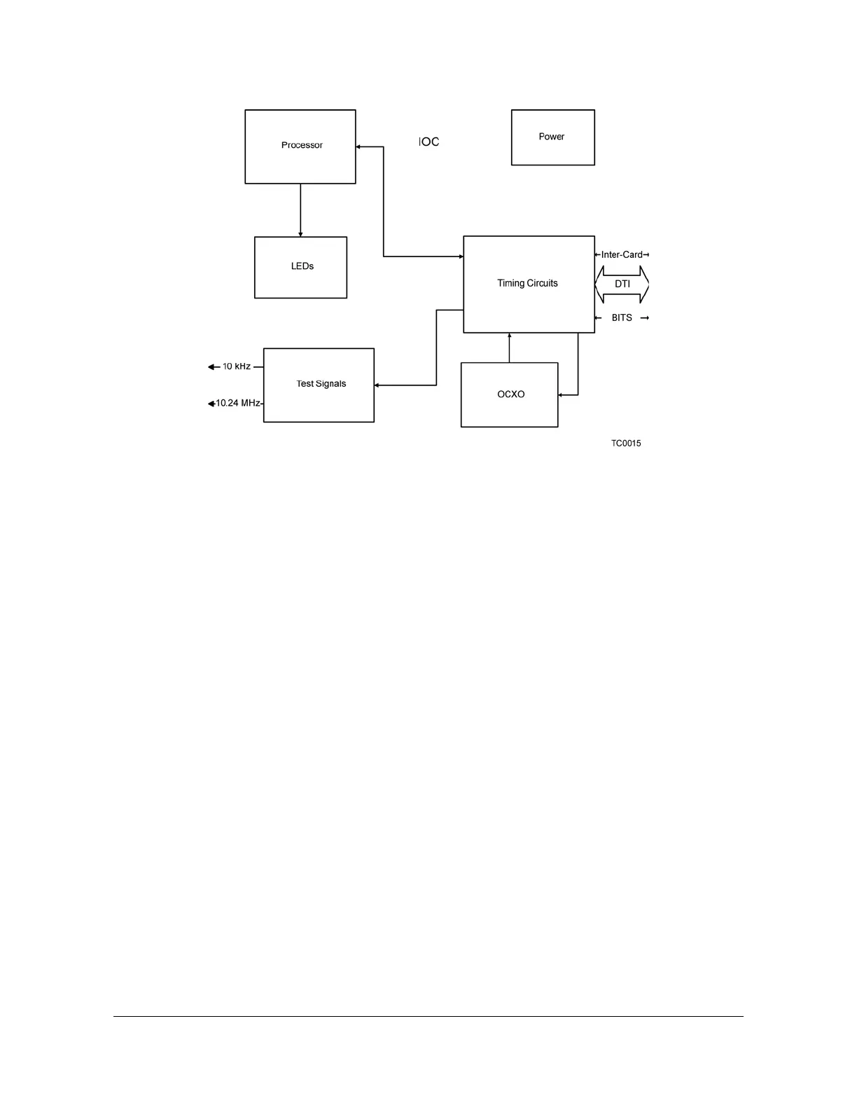
Figure 1-7. IOC Module Block Diagram
IOC Module
The IOC module has LED status indicators and test outputs for the system. The
LEDs indicate:
Power Status
Active Status
Output Status
External Reference Status
Alarm Status
Holdover Status
The test output connectors provide a 10.24 MHz master clock signal and a 10 kHz
DTI frame clock signal.
IMC Module
Connectors for Ethernet management, NTP time server, EIA-232 serial, and the
Two-Way GPS Timing Antenna connections are located on the IMC module. The
IMC’s LEDs indicate the following:
Power Status
Alarm Status
GPS Signal Status
 Loading...