097-93100-01 Revision C – February, 2010 TimeCreator 1000 User’s Guide 53
Chapter 3 Installing the TimeCreator 1000
Making Signal Connections
Making Signal Connections
The connectors for the GPS input signal, Management and NTP Server Ethernet
connections, and EIA-232 serial connection are located on the IMC module. The
rear panel has RJ-45 connectors for ten client DTI links, two DTI client/server links,
and two T1/E1 BITS frequency links.
Making Communications Connections
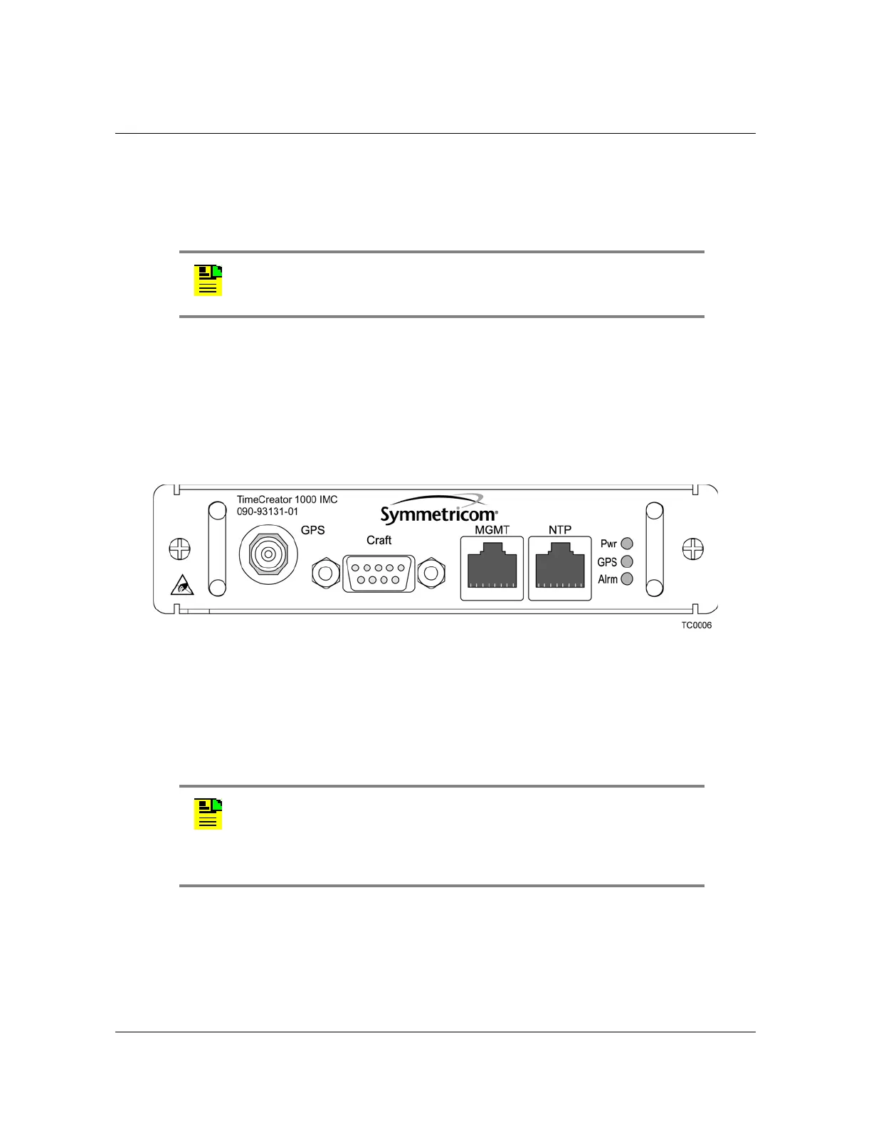
The IMC allows user control of the TimeCreator 1000. The EIA-232 serial port,
Ethernet Management port, and NTP server port are located on the IMC as shown
in Figure 3-2. See Working With Modules, on page 51 for module installation
instructions.
Figure 3-2. IMC Module
Ethernet Management and NTP Server Ports
The Ethernet Management and NTP server ports are standard
10Base-T/100Base-T shielded RJ-45 receptacles. To connect the TimeCreator
1000 to an Ethernet network, and to connect the NTP server to an NTP client, use
shielded twisted pair Ethernet RJ-45 cable.
Note: The T1/E1 BITS links do not function in this release.
Note: Continuing improvements to the design of the TimeCreator
1000 have lowered the level of emissions. UTP cable can be used for
DTI links with TimeCreator 1000 chassis revisions E or greater
(revision is on label on bottom of shelf). UTP cable can be used for
Ethernet connections to IMCs of revision H or later.
 Loading...