56 TimeCreator 1000 User’s Guide 097-93100-01 Revision C – February, 2010
Chapter 3 Installing the TimeCreator 1000
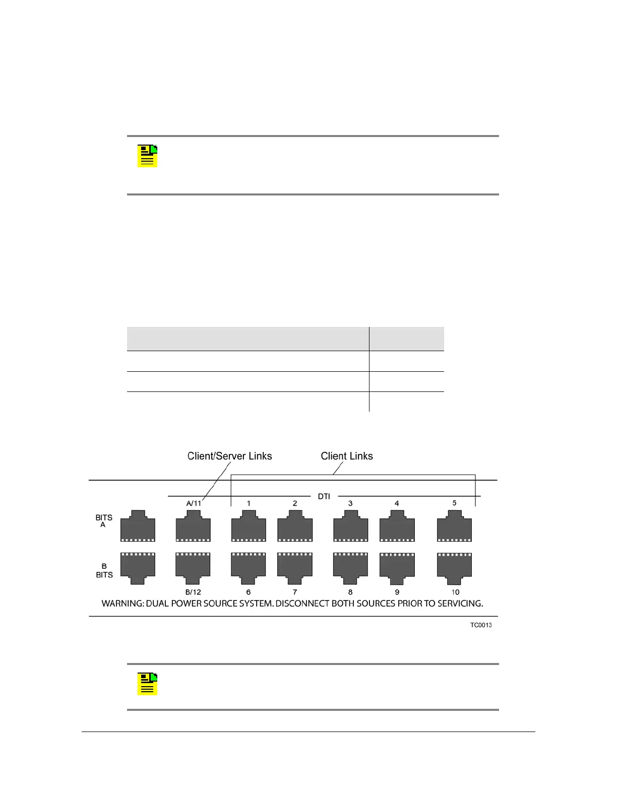
Making Signal Connections
To connect a TimeCreator 1000 root server to a subtending server, install a shielded
twisted pair RJ-45 cable, CAT5E or better, from the root server's rear panel DTI
connector to the subtending server's client input port (port A or port B, when
optioned as 'client').
If the root server in a DTI network with subtending servers is set to user mode to
utilize root server recovery, a connection should be made from the root server port
12 to a subtending server port 1. This enables root server recovery, in an orderly
manner, from any outages affecting the root server
The connector pinouts are listed in Table 3-3.
Figure 3-4. Rear Panel DTI Links
Note: Continuing improvements to the design of the TimeCreator
1000 have lowered the level of emissions. UTP cable can be used for
DTI links with TimeCreator 1000 chassis revisions E or greater
(revision is on label on bottom of shelf).
Table 3-3. DTI and Root DTI Connector Pin Assignments
Signal Name Pin
SIG+ (Positive Side of Transmitted/Received Data) 1
SIG– (Negative Side of Transmitted/Received Data) 2
Not Used 3, 4, 5, 6, 7, 8
Note: The 8-port option only uses Ports 1 through 6, A/11 and B/12.
Ports 7 through 10 cannot be enabled for this option.
 Loading...