097-93100-01 Revision C – February, 2010 TimeCreator 1000 User’s Guide 59
Chapter 3 Installing the TimeCreator 1000
Installation Check List
Installation Check List
To verify that the installation of the TimeCreator 1000 is complete, perform the
checks and procedures in Table 3-4.
Applying Power to the TimeCreator 1000
The TimeCreator 1000 is not equipped with a Power switch. DC power is controlled
by a power distribution panel. AC power is applied when a standard 120 or 220
V AC power cord connected to the 100-240 AC Power module is plugged into the
appropriate power outlet.
Normal Power Up Indications
As the TimeCreator 1000 powers up and begins normal operation, the IOC module
and IMC module LEDs all turn on. After the module self-test is complete and the
module firmware is operational, the LED states may change to indicate the
appropriate state or status.
Table 3-5 provides a description of the module LEDs.
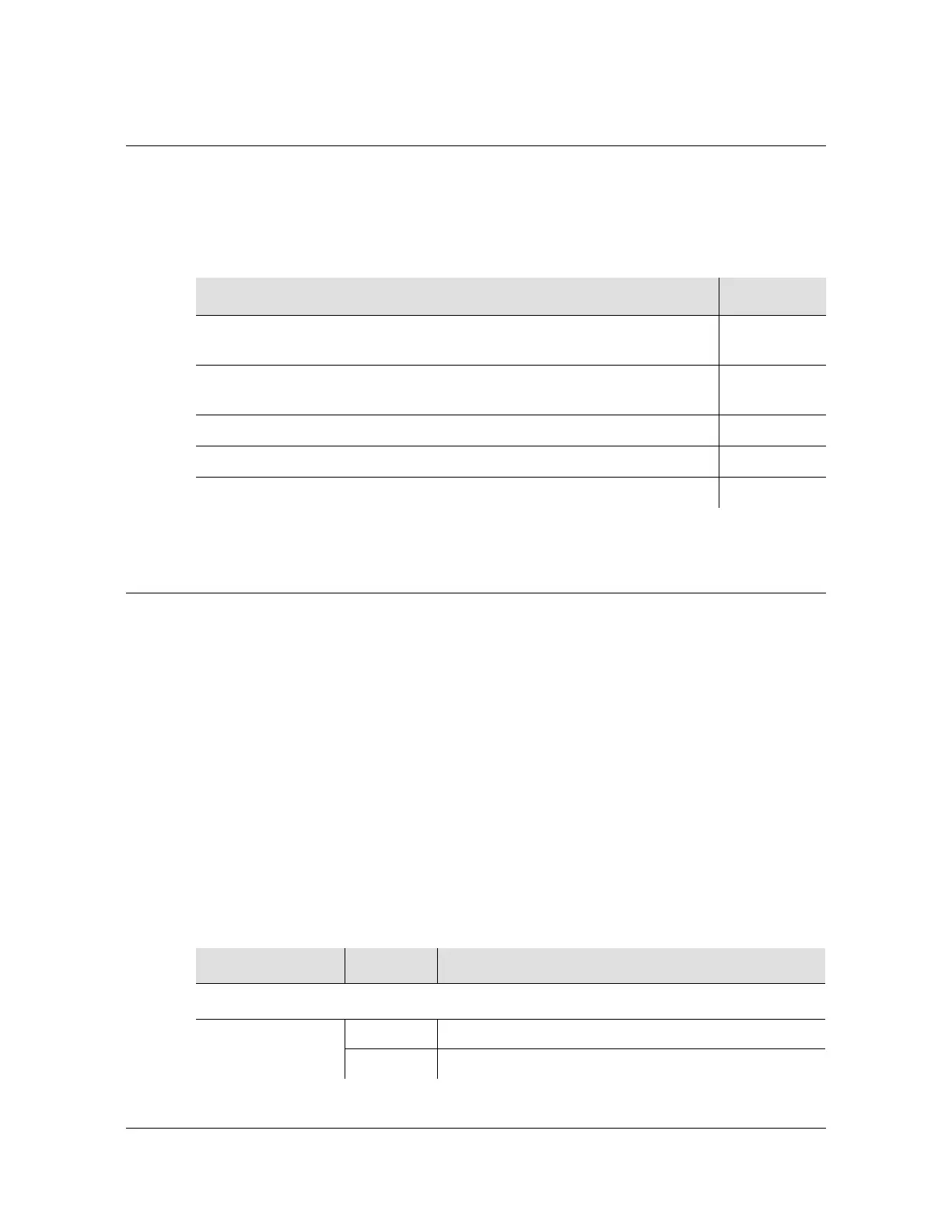
Table 3-4. Installation Completeness Checklist
Operation Complete
Ensure the TimeCreator 1000 chassis is securely attached to mounting
rack
Ensure that the appropriate modules (and filler panels if needed) are
installed
Verify that all power and ground wires are installed correctly and securely
Verify that all communications cables are properly installed
Verify that all input and output cables are properly installed
Table 3-5. Module LED Descriptions
LED Color Description
Power Module
Status Off Power input not connected or Power Module Failure
Green Power Module is functioning properly
 Loading...