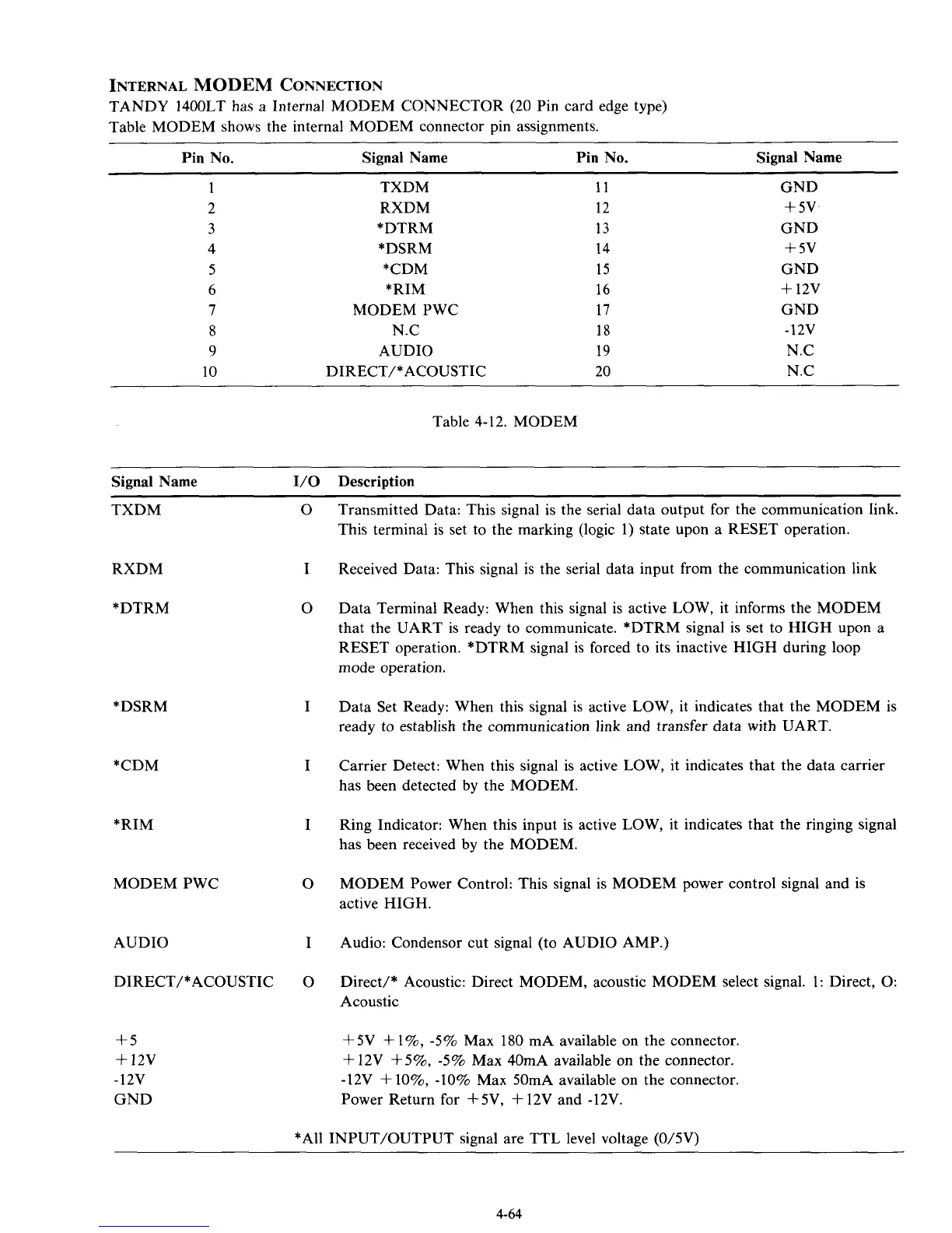
INTERNAL
MODEM
CONNECTION
TANDY 1400LT has a Internal MODEM CONNECTOR (20 Pin card edge type)
Table MODEM shows the internal MODEM connector pin assignments.
Signal Name
Pin No. Signal Name Pin No.
1
2
3
4
5
6
7
8
9
10
TXDM
RXDM
*DTRM
*DSRM
*CDM
*RIM
MODEM PWC
N.C
AUDIO
DIRECT/* ACOUSTIC
11
12
13
14
15
16
17
18
19
20
GND
+
5v
GND
+
5v
GND
+
12v
GND
-12v
N.C
N.C
Table 4-12. MODEM
Signal Name
I/O
Description
TXDM
RXDM
*DTRM
*DSRM
*CDM
*RIM
MODEM PWC
AUDIO
DIRECT/* ACOUSTIC
+5
+
12v
-12v
GND
0
I
0
I
I
I
0
I
0
Transmitted Data: This signal is the serial data output for the communication link.
This terminal is set to the marking (logic 1) state upon a RESET operation.
Received Data: This signal is the serial data input from the communication link
Data Terminal Ready: When this signal is active LOW, it informs the MODEM
that the UART is ready to communicate. *DTRM signal is set to HIGH upon a
RESET operation. *DTRM signal is forced to its inactive HIGH during loop
mode operation.
Data Set Ready: When this signal is active LOW, it indicates that the MODEM is
ready to establish the communication link and transfer data with UART.
Carrier Detect: When this signal is active LOW, it indicates that the data carrier
has been detected by the MODEM.
Ring Indicator: When this input is active LOW, it indicates that the ringing signal
has been received by the MODEM.
MODEM Power Control: This signal is MODEM power control signal and is
active HIGH.
Audio: Condensor cut signal (to AUDIO AMP.)
Direct/* Acoustic: Direct MODEM, acoustic MODEM select signal. 1: Direct,
0:
Acoustic
+5V
+
1%, -5% Max
180
mA available
on
the connector.
+
12V
+5%,
-5% Max 40mA available
on
the connector.
-12V
+
lo%, -10% Max 50mA available
on
the connector.
Power Return for +5V,
+
12V and -12V.
*All INPUT/OUTPUT signal are TTL level voltage (0/5V)
4-64