IV-19.
Speaker
Circuit
The system unit has a 28mm (1.linch) audio speaker. The speaker control circuits and driver are
on
the
MAIN
PCB. The speaker driver is capable of about 0.2 watts of power. The control circuits allow the speaker to be driven
three different methods.
1.
Direct program control with an
I/O
address, 61H bit
1,
may be toggled to generate a tone pulse.
2.
Output from Channel
2
of the timer counter, may be programmed to generate a tone pulse.
3.
PRCLK clock input to timer counter can be modulated with an
1/0
address, 61H bit
0.
Volume Control
The speaker output level is controlled by the variable resister that is located in the battery compartmet. By turning
it clockwise, you can increase the speaker output, and by turning it counter clockwise, you can decrease the speaker
output.
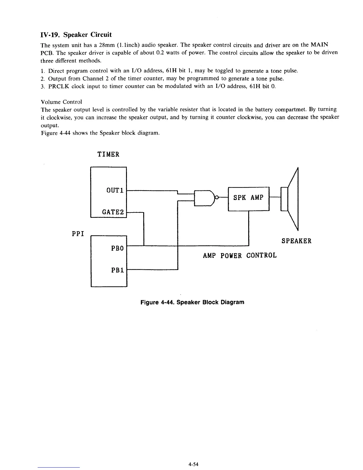
Figure 4-44 shows the Speaker block diagram.
TIMER
OUT1
*
SPK AMP
-
GATE2
PPI
SPEAKER
Figure
4-44.
Speaker Block Diagram
4-54