12V
Output Voltage Circuit
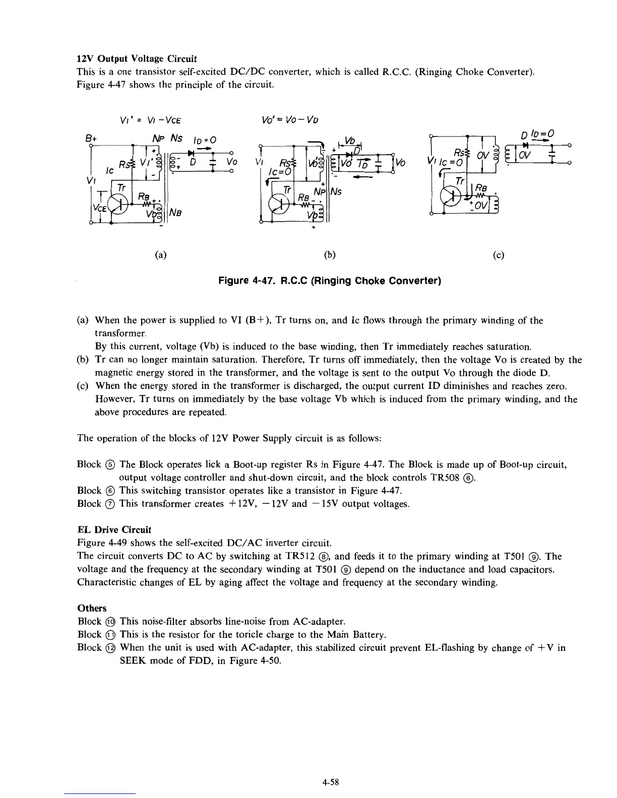
This is a one transistor self-excited DC/DC converter, which
is
called R.C.C. (Ringing Choke Converter).
Figure 4-47 shows the principle of the circuit.
VI’=
VI
-VCE
vo’
=
VO
-
VO
--
+
Figure 4-47. R.C.C (Ringing Choke Converter)
(a) When the power is supplied to VI (BS), Tr turns on, and
IC
flows through the primary winding of the
transformer.
By this current, voltage (Vb) is induced to the base winding, then Tr immediately reaches saturation.
(b)
Tr can no longer maintain saturation. Therefore, Tr turns off immediately, then the voltage Vo is created by the
magnetic energy stored in the transformer, and the voltage is sent to the output Vo through the diode
D.
(c) When the energy stored in the transformer is discharged, the output current ID diminishes and reaches zero.
However, Tr turns on immediately by the base voltage Vb which is induced from the primary winding, and the
above procedures are repeated.
The operation of the blocks of 12V Power Supply circuit is as follows:
Block
@
The Block operates lick
a
Boot-up register Rs in Figure 4-47. The Block is made up of Boot-up circuit,
Block
0
This switching transistor operates like a transistor in Figure 4-47.
Block
(?J
This transformer creates
+
12V,
-
12V and
-
15V output voltages.
output voltage controller and shut-down circuit, and the block controls TR508
0.
EL
Drive Circuit
Figure 4-49 shows the self-excited DC/AC inverter circuit.
The circuit converts DC to AC by switching at TR512
@,
and feeds it to the primary winding at T501
@.
The
voltage and the frequency at the secondary winding at
T501
@
depend on the inductance and load capacitors.
Characteristic changes of
EL
by aging affect the voltage and frequency at the secondary winding.
Others
Block
@
This noise-filter absorbs line-noise from AC-adapter.
Block
0
This is the resistor for the toricle charge to the Main Battery.
Block
@
When the unit is used with AC-adapter, this stabilized circuit prevent EL-flashing by change of +V in
SEEK
mode of FDD, in Figure 4-50.
4-58