IV-7. RAM
Control Circuit
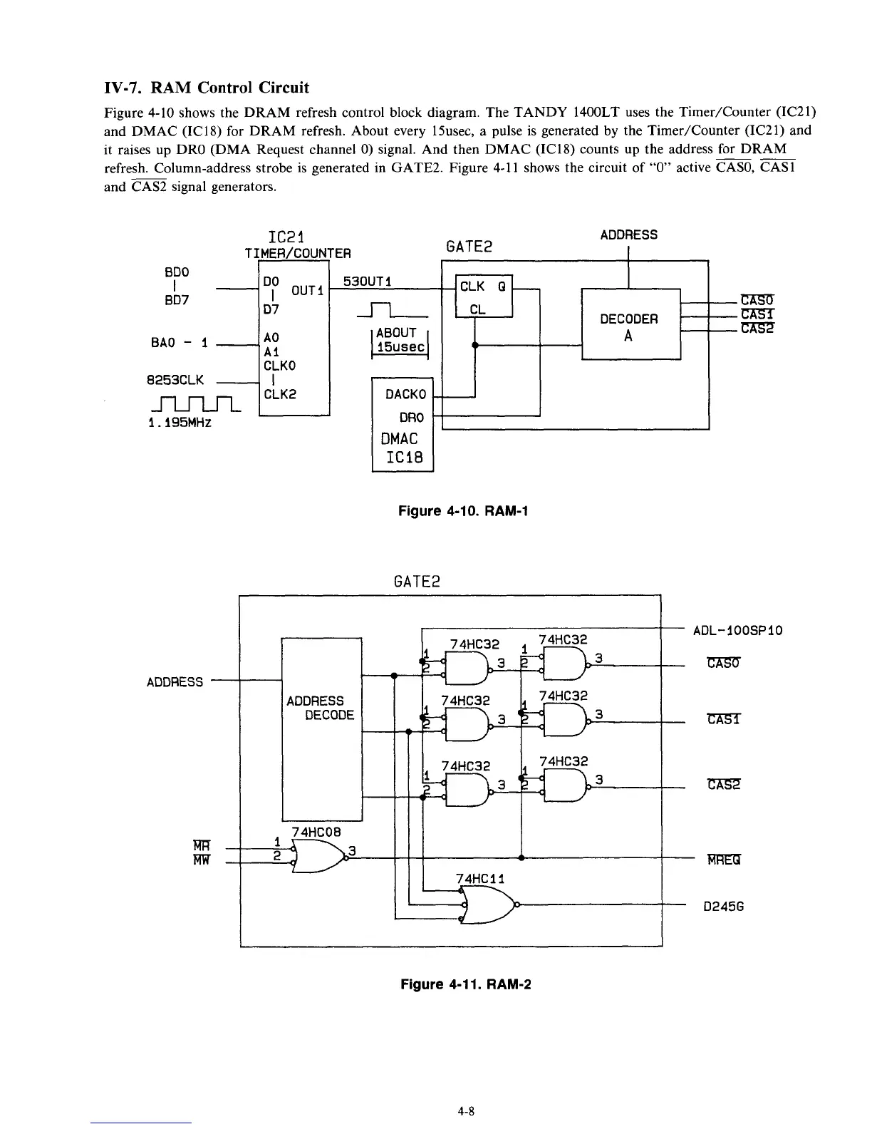
Figure 4-10 shows the DRAM refresh control block diagram. The TANDY 1400LT uses the TimerKounter (IC21)
and DMAC (IC18) for DRAM refresh. About every 15usec, a pulse
is
generated by the Timer/Counter (IC21) and
it raises up DRO (DMA Request channel
0)
signal. And then DMAC (IC18) counts up the address for DRAM
refresh. Column-address strobe is generated in GATE%. Figure 4-1
1
shows
the circuit of
“0”
active CASO, CAS1
and CAS2 signal generators.
--
T
BDO
I
BD7
BAO
-
I
-
8253CLK
-
m
1.195MHz
ADDRESS
-
m-
FW-
IC2
1
UIER/COUN
Dr
OUTI
D7
A0
AI
CLKO
I
CLK2
ADDRESS
GATE2
3
I
I
DACKO
DMAC
IC18
Figure 4-10. RAM-1
GATE2
ADL-IOOSPIO
mm
rn
C7is.2
uKE7l
D245G
Figure 4-1 1. RAM-2
4-
8