5.
Operation
Procedure
DISK LOADING/EJECTING
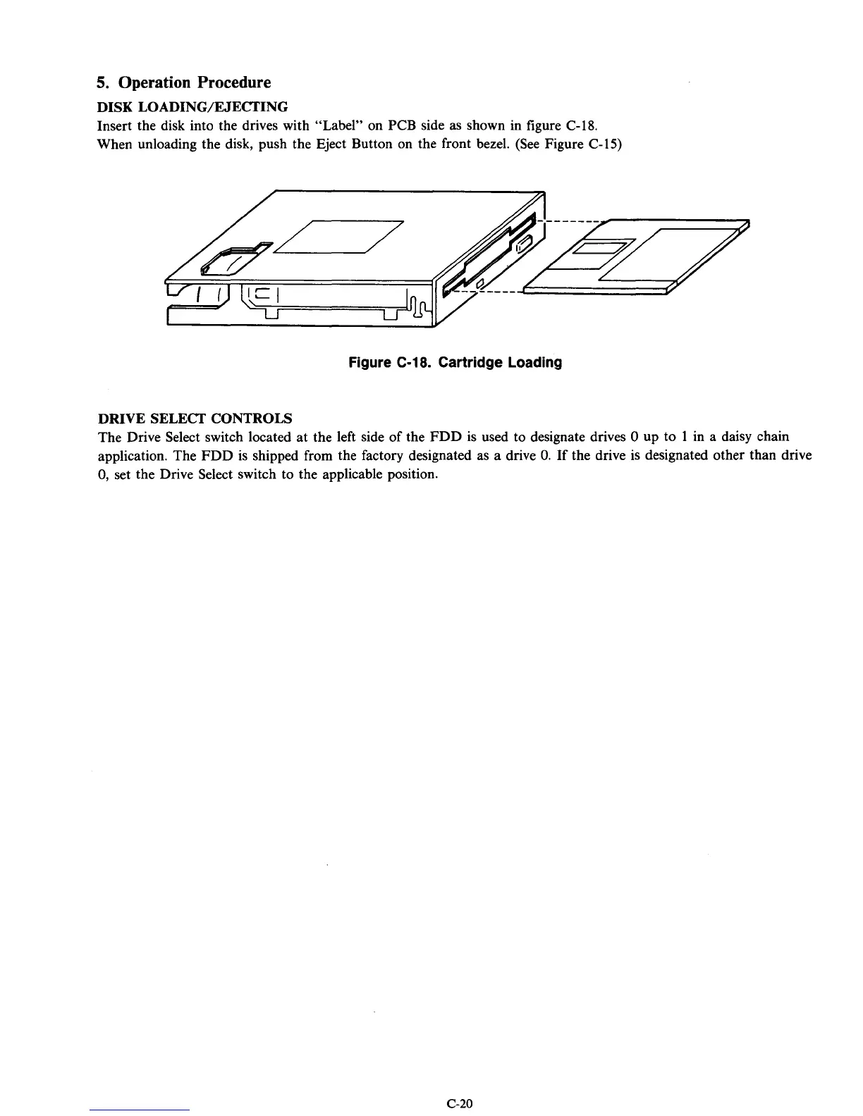
Insert the disk into the drives with “Label” on PCB side as shown in figure C-18.
When unloading the disk, push the Eject Button
on
the front bezel. (See Figure C-15)
Figure
C-18.
Cartridge Loading
DRIVE SELECT CONTROLS
The Drive Select switch located at the left side of the FDD is used to designate drives
0
up to
1
in a daisy chain
application. The FDD is shipped from the factory designated as a drive
0.
If
the drive is designated other than drive
0,
set the Drive Select switch to the applicable position.
c-20