(8)
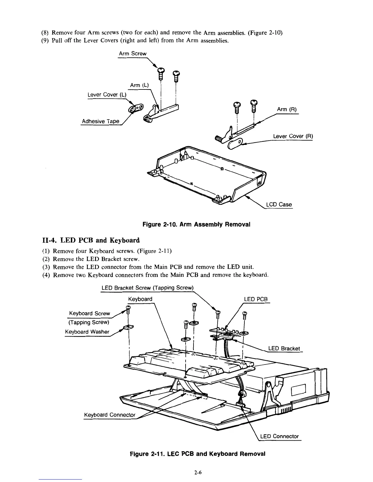
Remove four Arm screws (two for each) and remove the Arm assemblies. (Figure 2-10)
(9)
Pull
off
the Lever Covers (right and left) from the Arm assemblies.
Lever Cover
(R)
Figure 2-10. Arm Assembly Removal
11-4.
LED
PCB
and Keyboard
(1)
Remove four Keyboard screws. (Figure 2-1
1)
(2) Remove the LED Bracket screw.
(3)
Remove the LED connector from the Main PCB and remove the
LED
unit.
(4)
Remove two Keyboard connectors from the Main PCB and remove the keyboard.
LED
Bracket Screw (TaDDina Screw)
\
LED
Connector
Figure
2-1 1.
LEC
PCB
and Keyboard Removal
2-6