LCD
Unit Interface
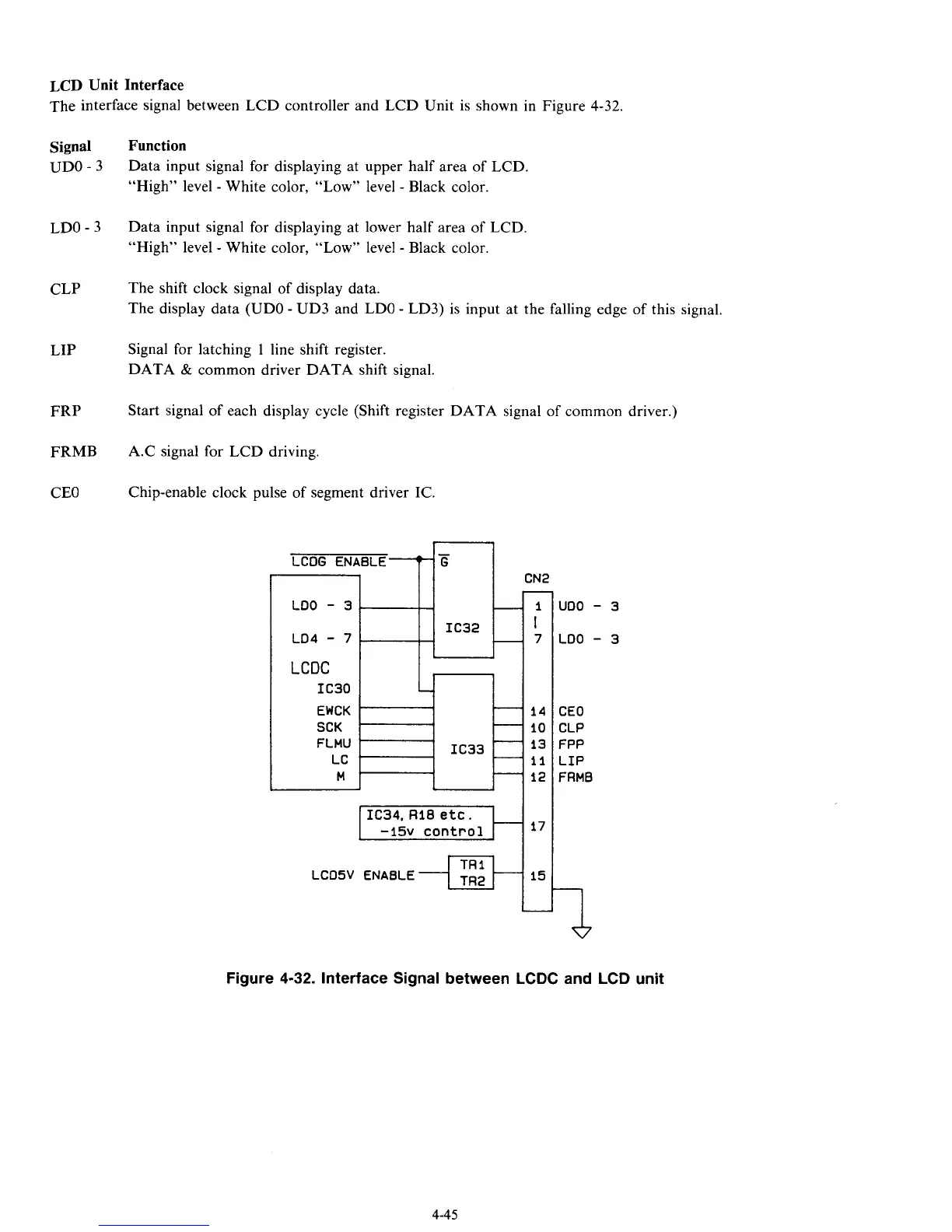
The interface signal between LCD controller and LCD Unit is shown in Figure 4-32.
LCDC
IC30
EWCK
SCK
FLMU
LC
M
Signal
UDO
-
3
LDO
-
3
CLP
LIP
FRP
FRhlB
CEO
-
’
-
-
-
IC33
.
-
-
Function
Data input signal for displaying at upper half area of LCD.
“High” level
-
White color, “Low” level
-
Black color.
Data input signal for displaying at lower half area of LCD.
“High” level
-
White color, “Low” level
-
Black color.
The shift clock signal of display data.
The display data (UDO
-
UD3 and LDO
-
LD3) is input at the falling edge of this signal.
Signal for latching
1
line shift register.
DATA
&
common driver DATA shift signal.
Start signal of each display cycle (Shift register DATA signal of common driver.)
A.C signal for LCD driving.
Chip-enable clock pulse of segment driver IC.
LCOG ENABLE
LOO
-
3
CN2
IC32
@
14
10
13
11
12
I
IC34.
RIB
etc.
LCOSV ENABLE +-E-q15
I
uoo
-
3
LOO
-
3
CEO
CLP
FPP
LIP
FAMB
a
Figure
4-32.
Interface Signal between LCDC and LCD unit
4-45