The UART (IC35) contains a programmable Baud Rate Generator.
The output frequency of the Baud Rate Generator is 16x the baud rate
[
divisor
#
=
(frequency input)/(baud rate
X
16)]. Two 8 bit latches store the divisor in a 16 bit binary format. These Divisior latches must be loaded during
initialization in order to ensure desired operation of the Baud Rate Generator.
Table 4-10 shows the use
of
the Baud Rate Generator with crystal frequency of 1.8432 MHz
.
m
m
Percent En
or
Difference
Between Desired and
Actual
Divisor Used to
Generate
16
X
Clock
Desired Baud Rate
SELECTOR
Hr
B
,
ti
MODm
50
75
110
134.5
150
300
600
1200
1800
2000
2400
3
600
4800
7200
9600
2304
1536
1047
857
768
3 84
192
96
64
58
48
32
24
16
12
-
0.026
0.058
-
0.69
Table 4-10. Baud Rate Generator (1.8432
MHz)
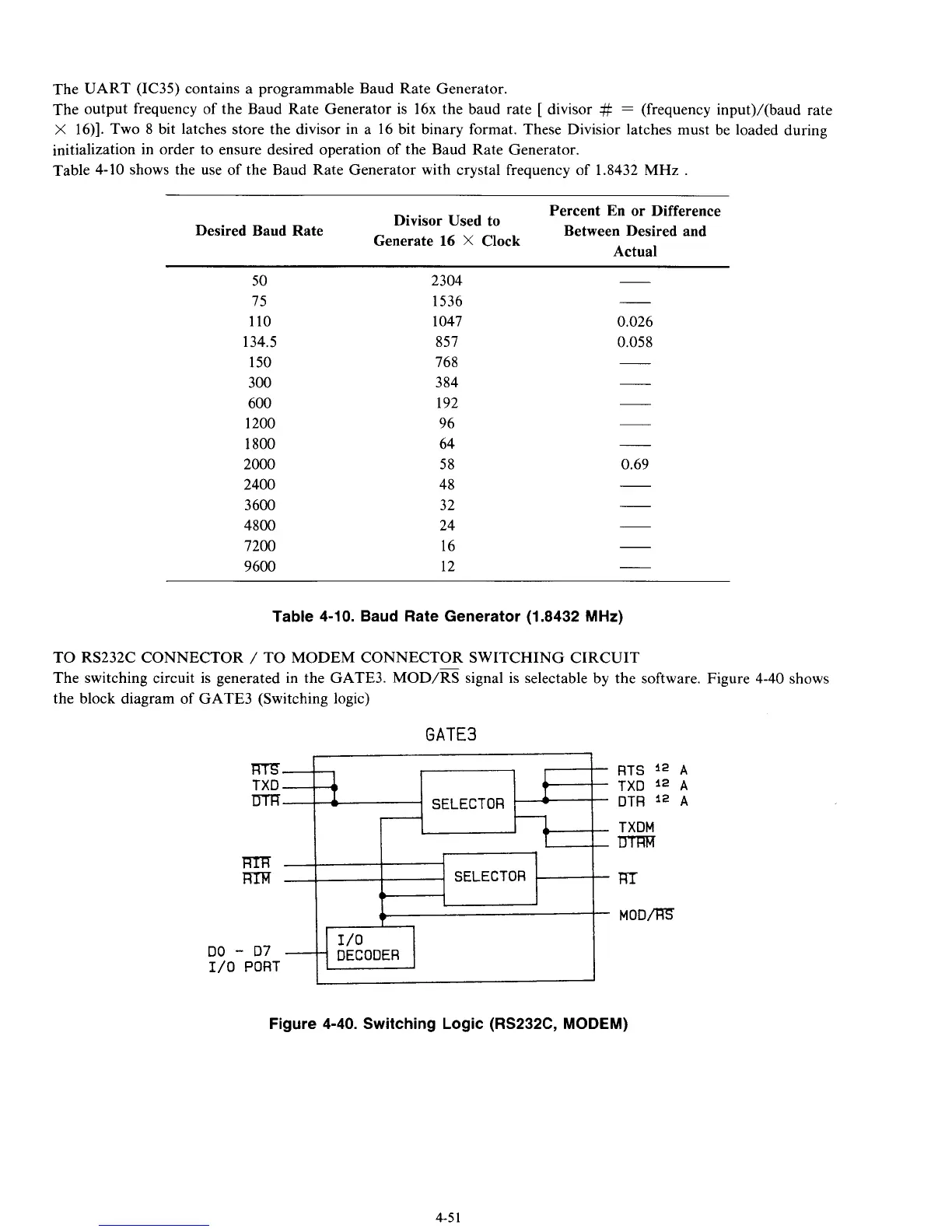
TO
RS232C CONNECTOR
/
TO MODEM CONNECTOR SWITCHING CIRCUIT
The switching circuit is generated in the GATE3. MOD/m signal is selectable by the software. Figure 4-40 shows
the block diagram of GATE3 (Switching logic)
GATE3
RTS
l2
A
TXD
l2
A
SELECTOR
DTR
l2
A
TXDM
m
DO
-
D7
$1
DE
C
0
DER
1/0
PORT
Figure 4-40. Switching Logic (RS232C, MODEM)
4-5
1