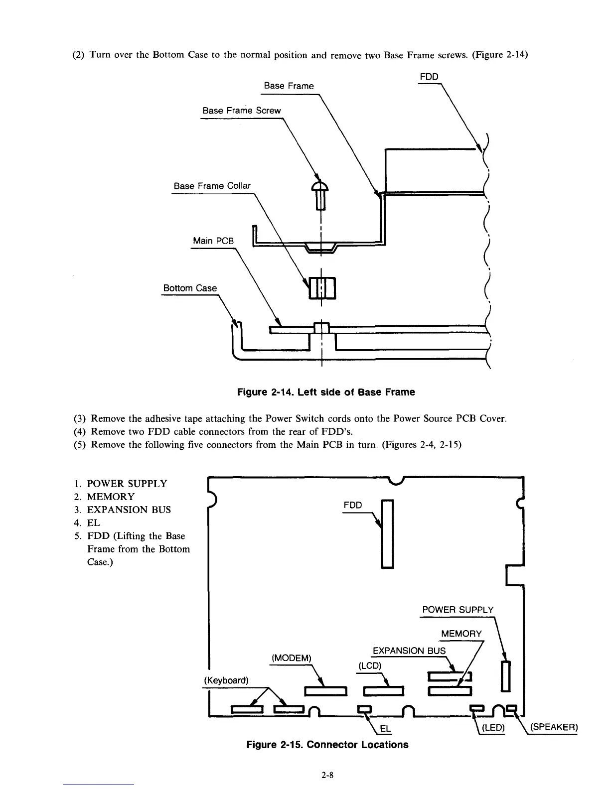
(2)
Turn over the Bottom Case to the normal position and remove two Base Frame screws. (Figure 2-14)
Base Frame
\
Base Frame Screw
\
Base Frame Collar
Main PCB
n\
Figure 2-14. Left side of Base Frame
(3)
Remove the adhesive tape attaching the Power Switch cords
onto
the Power Source PCB Cover.
(4)
Remove two FDD cable connectors from the rear of FDD's.
(5)
Remove the following five connectors from the Main PCB in turn. (Figures 2-4,
2-15)
2.
MEMORY
3.
EXPANSION
BUS
4.
EL
5.
FDD (Lifting the Base
Frame from the Bottom
Case.)
(Keyboard)
L
POWER SUPPLY
-\
Figure
2-1 5.
Connector Locations
\(SPEAKER)
1. POWER SUPPLY
I
1
2-8