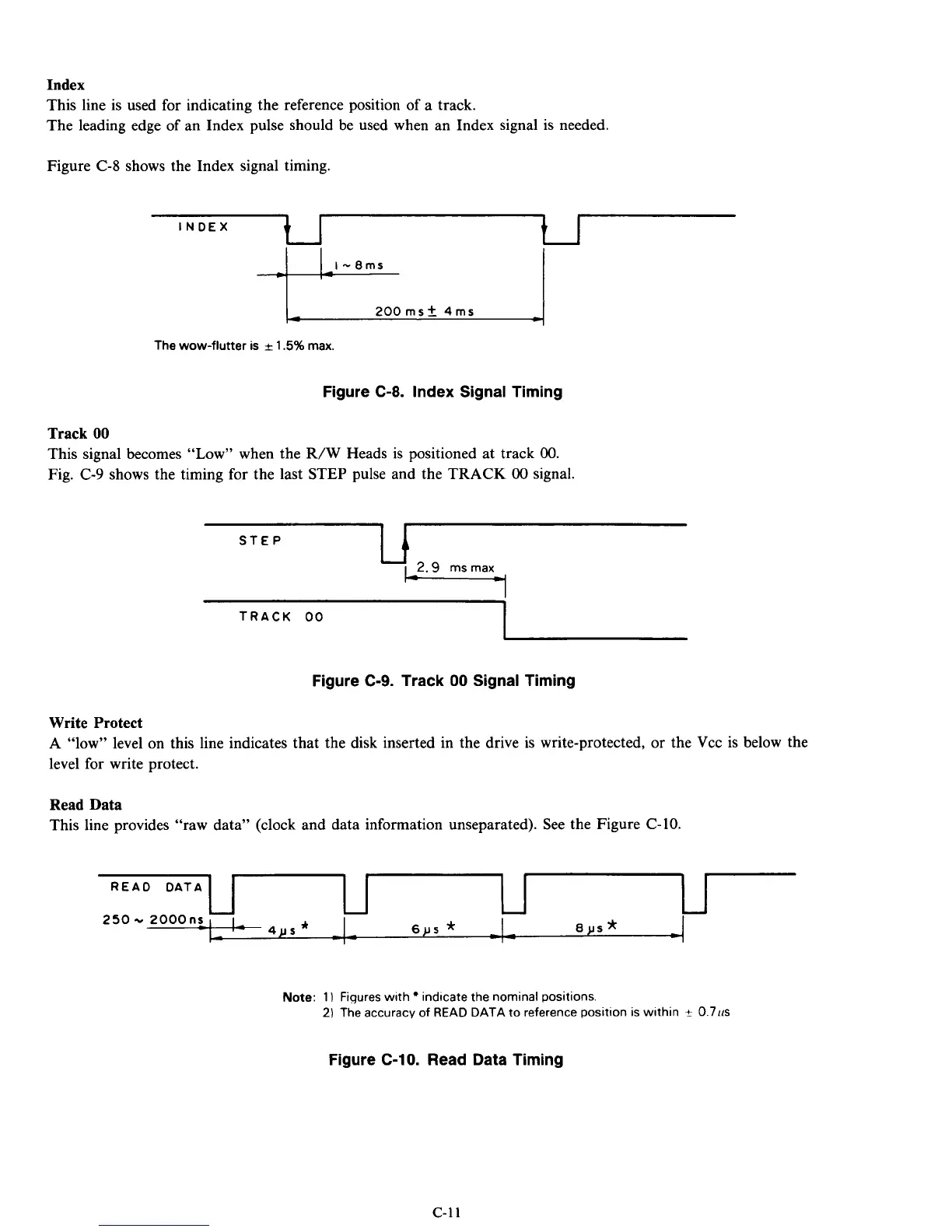
Index
This line is used for indicating the reference position of a track.
The leading edge of an Index pulse should be used when an Index signal is needed.
L
READ DATA
-
6ps
*
Figure C-8 shows the Index signal timing.
-
d
8JlS
*
)r=
-
INDEX
The
wow-flutter
is
r
1.5%
max.
Figure C-8. Index Signal Timing
Track
00
This signal becomes “Low” when the R/W Heads is positioned at track
00.
Fig. C-9 shows the timing for the last STEP pulse and the TRACK
00
signal.
STEP
TRACK
00
1
Figure
C-9.
Track
00
Signal Timing
Write Protect
A “low” level on this line indicates that the disk inserted in the drive
is
write-protected,
or
the Vcc is below the
level for write protect.
Read Data
This line provides “raw data” (clock and data information unseparated). See the Figure C-10.
Note:
1
)
Ftqures with indicate the nominal positions
2)
The accuracy
of
READ
DATA
to reference position is within
+
0
711s
Figure
C-10.
Read Data Timing
c-11