IV-21.
Option
EXPANSION BUS (Option Interface card)
The interface card is a small card installed into the expansion bus connector accessed at the rear of the TANDY
1400LT.
This card relays signals transferred between the TANDY 1400LT system board and optional expansion box.
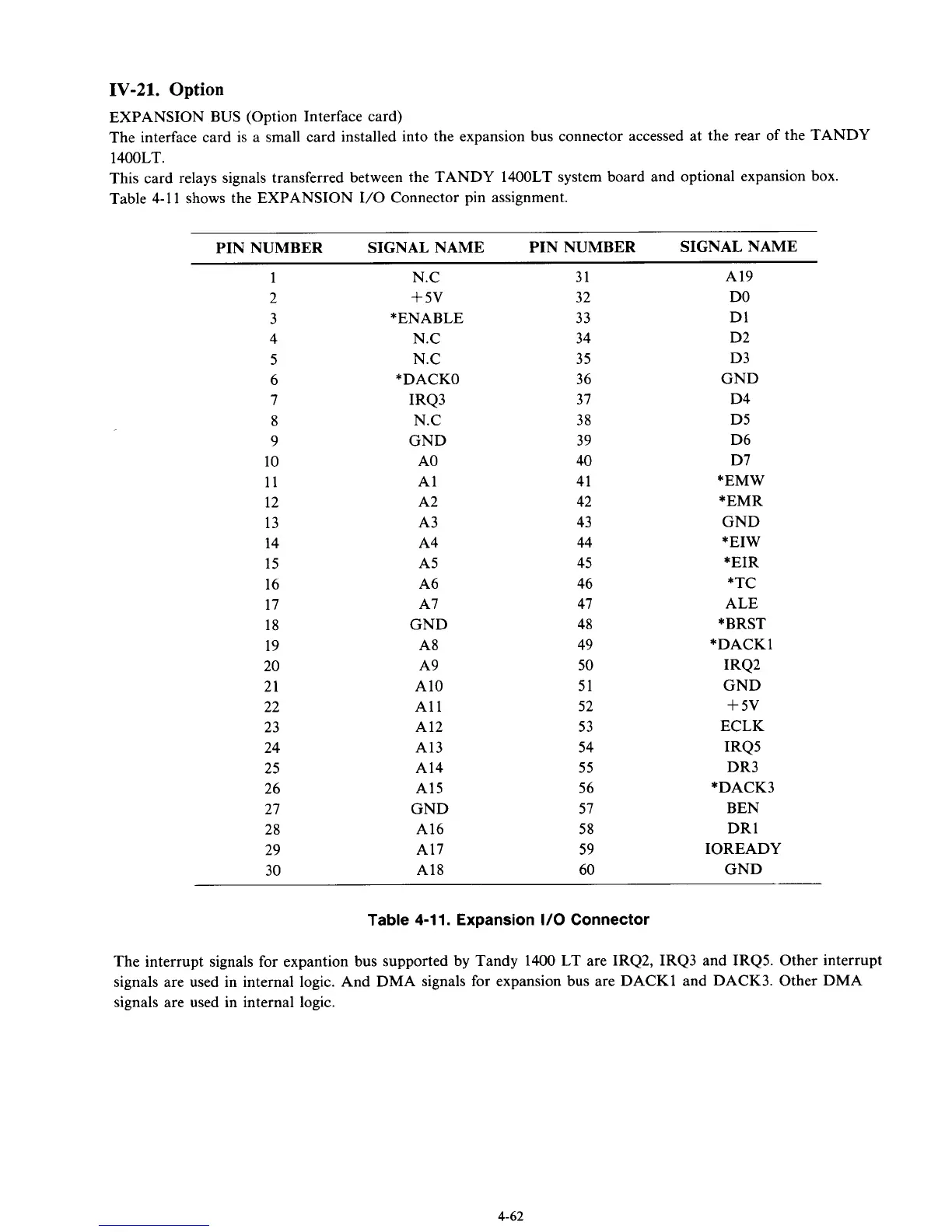
Table 4-11 shows the EXPANSION I/O Connector pin assignment.
PIN NUMBER SIGNAL NAME PIN NUMBER SIGNAL NAME
1
2
3
4
5
6
7
8
9
10
11
12
13
14
15
16
17
18
19
20
21
22
23
24
25
26
27
28
29
30
N.C
+
5v
*ENABLE
N.C
N.C
*DACKO
IRQ3
N.C
GND
A0
A1
A2
A3
A4
A5
A6
A7
GND
A8
A9
A10
A1 1
A12
A13
A14
A15
GND
A16
A17
A18
31
32
33
34
35
36
37
38
39
40
41
42
43
44
45
46
47
48
49
50
51
52
53
54
55
56
57
58
59
60
A19
DO
D1
D2
D3
GND
D4
D5
D6
D7
*EMW
*EMR
GND
*EIW
*EIR
*TC
ALE
*BRST
*DACK 1
IRQ2
GND
+
5v
ECLK
IRQ5
DR3
*DACK3
BEN
DR 1
IOREADY
GND
Table
4-1
1. Expansion
I/O
Connector
The interrupt signals for expantion bus supported by Tandy 1400 LT are IRQ2, IRQ3 and IRQ5. Other interrupt
signals are used in internal logic. And DMA signals for expansion bus are DACKl and DACK3. Other DMA
signals are used in internal logic.
4-62