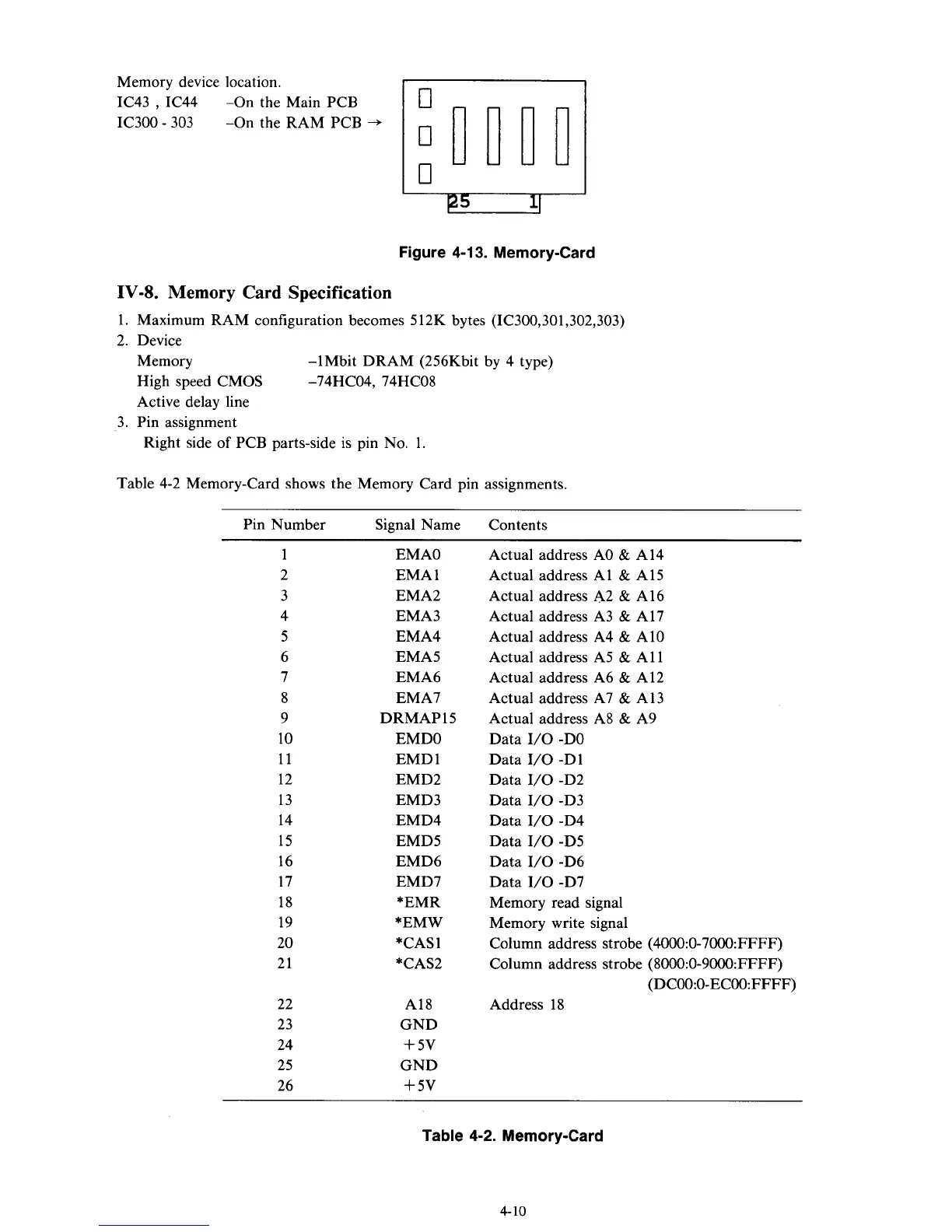
Memory device location.
IC43
,
IC44
IC300
-
303
-On the Main PCB
-On the RAM PCB
-+
Figure
4-1
3.
Memory-Card
IV-8.
Memory
Card
Specification
1. Maximum RAM configuration becomes
5
12K bytes (IC300,301,302,303)
2. Device
Memory
Active delay line
-lMbit DRAM (256Kbit by 4 type)
High speed CMOS -74HC04, 74HC08
3. Pin assignment
Right side
of
PCB parts-side is pin
No.
1.
Table 4-2 Memory-Card shows the Memory Card pin assignments.
Pin Number Signal Name Contents
1
2
3
4
5
6
7
8
9
10
11
12
13
14
15
16
17
18
19
20
21
22
23
24
25
26
EMAO
EMA 1
EMA2
EMA3
EMA4
EMA5
EMA6
EMA7
DRMAP 15
EMDO
EMD 1
EMD2
EMD3
EMD4
EMD5
EMD6
EMD7
*EMR
*EMW
*CAS
1
*CAS2
A18
GND
+
5v
GND
+
5v
Actual address A0
&
A14
Actual address A1
&
A15
Actual address A2
&
A16
Actual address A3
&
A17
Actual address A4
&
A10
Actual address A5
&
A1 1
Actual address A6
&
A12
Actual address A7
&
A13
Actual address A8
&
A9
Data I/O -DO
Data I/O -D1
Data
I/O
-D2
Data
1/0
-D3
Data
1/0
-D4
Data
I/O
-D5
Data I/O -D6
Data I/O -D7
Memory read signal
Memory write signal
Column address strobe (4000:0-7000:FFFF)
Column address strobe (8000:0-9000:FFFF)
Address 18
(DC00:O-ECOO:FFFF)
Table
4-2.
Memory-Card
4-10