IV-6.
MEMORY
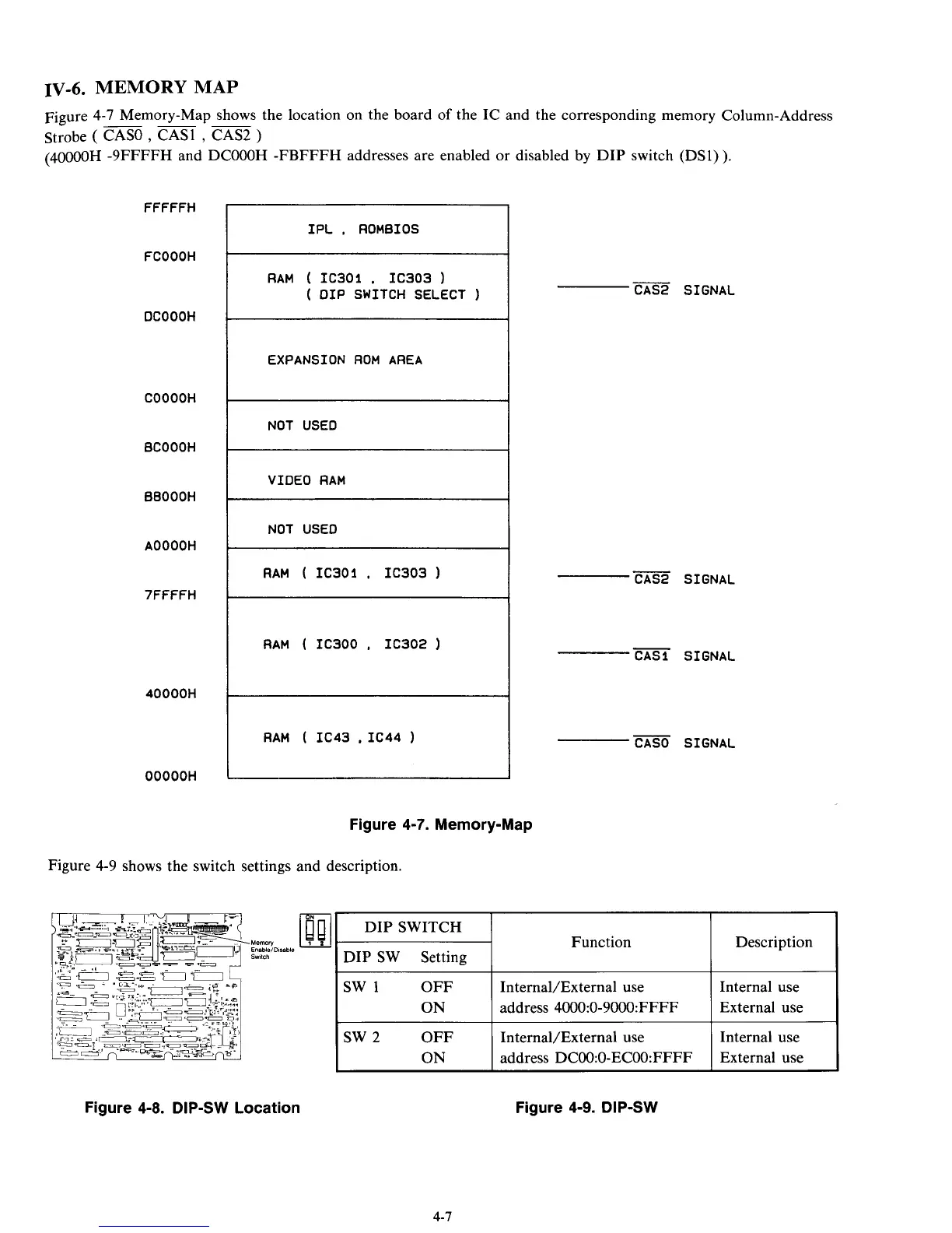
MAP
Figure 4-7 Memory-Map shows the location on the board
of
the IC and the corresponding memory Column-Address
Strobe
(
CASO
,
CASl
,
CAS2
)
-~~
FFFFFH
FCOOOH
DCOOOH
COOOOH
BCOOOH
BBOOOH
AOOOOH
7FFFFH
40000H
OOOOOH
IPL
,
ROMBIOS
(40000H -9FFFFH and DCOOOH -FBFFFH addresses are enabled or disabled by DIP switch (DS1)).
-
CAS2 SIGNAL
RAM
(
IC301
,
IC303
)
(
DIP SWITCH SELECT
)
EXPANSION
ROM
AREA
NOT USED
VIDEO
RAM
NOT USED
RAM
(
IC301
,
IC303
RAM
(
IC300
.
IC302
RAM
(
IC43
,
IC44
)
Figure
4-7.
Memory-Map
Figure 4-9 shows the switch settings and description.
-
CAS2 SIGNAL
-
CASl SIGNAL
-
CASO SIGNAL
Function Description
InternaVExternal use Internal use
address 4000:0-9000:FFFF External use
sw
2
InternaVExternal use Internal use
Figure
4-8.
DIP-SW Location
Figure
4-9.
DIP-SW
4-7