5V
Output
Voltage
Circuit
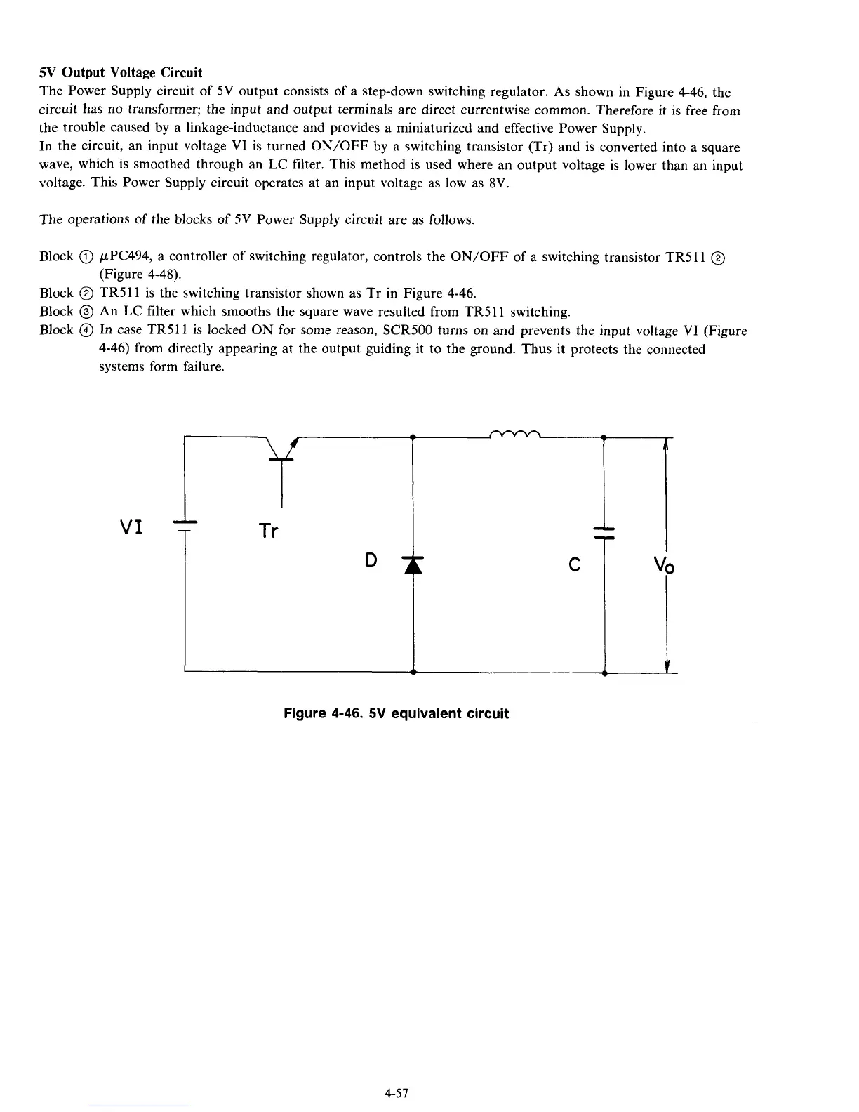
The Power Supply circuit of
5V
output consists of a step-down switching regulator.
As
shown in Figure 4-46, the
circuit has
no
transformer; the input and output terminals are direct currentwise common. Therefore
it
is free from
the trouble caused by a linkage-inductance and provides a miniaturized and effective Power Supply.
In
the circuit, an input voltage
VI
is turned ON/OFF by a switching transistor (Tr) and is converted into a square
wave, which is smoothed through
an
LC filter. This method is used where an output voltage is lower than an input
voltage. This Power Supply circuit operates at
an
input voltage as low as 8V.
The operations of the blocks of
5V
Power Supply circuit are as follows.
Block
@
pPC494, a controller of switching regulator, controls the ON/OFF of a switching transistor TR511
@
Block
@
TR5 11 is the switching transistor shown as Tr in Figure 4-46.
Block
@
An
LC filter which smooths the square wave resulted from TR511 switching.
Block
@
In
case TR511 is locked
ON
for some reason, SCRSOO turns
on
and prevents the input voltage
VI
(Figure
(Figure 4-48).
4-46) from directly appearing at the output guiding it to the ground. Thus it protects the connected
systems form failure.
D*
C
,
Figure
4-46.
5V
equivalent circuit
4-51