2-3
FAULT DIAGNOSIS
BY
FDD TESTER
FTS-1
2-3- 1 describes check method for normal operation in accordance with the predetermined procedures.
2-3-2 describes check points for abnormal operations which come out in accordance with the above procedures.
2-3-1
Normal Operation
Pre-setting:
1)
Refering to operation manual
of
FDD Tester FTS-1, connect the drive to FTS-1.
2) Set the drive select switch to
“0”.
3) Set the all the switches of FTS-1 to
“OFF”.
4)
Set the disk in the drive which is not write protected.
1. Power on and push “Reset” button
2. “MOTOR ON” switch on.
3. Eject the disk
4.
Load the disk
I
5.
Stepping (Confirm the step rate with
oscilloscope or counter)
6.
Track Positioning (Measure TS-1,2)
I.
The heads return to Track
00
and stop there.
!,
The Track
00
indicator lights.
I.
The spindle motor rotates (See the INDEX signal with oscilloscope)
l.
READY indicator lights in about
0.5
seconds after switch is on.
I.
The spindle motor stops rotating.
l.
READY indicator does not light.
I.
The spindle motor starts to rotate immidiately.
2.
READY indicator lights in about
0.5
seconds.
1.
Heads don’t move toward outer track when heads are located on
track
00.
2.
When the heads is set to any track other than Track
00,
Track
00
indicator does not light.
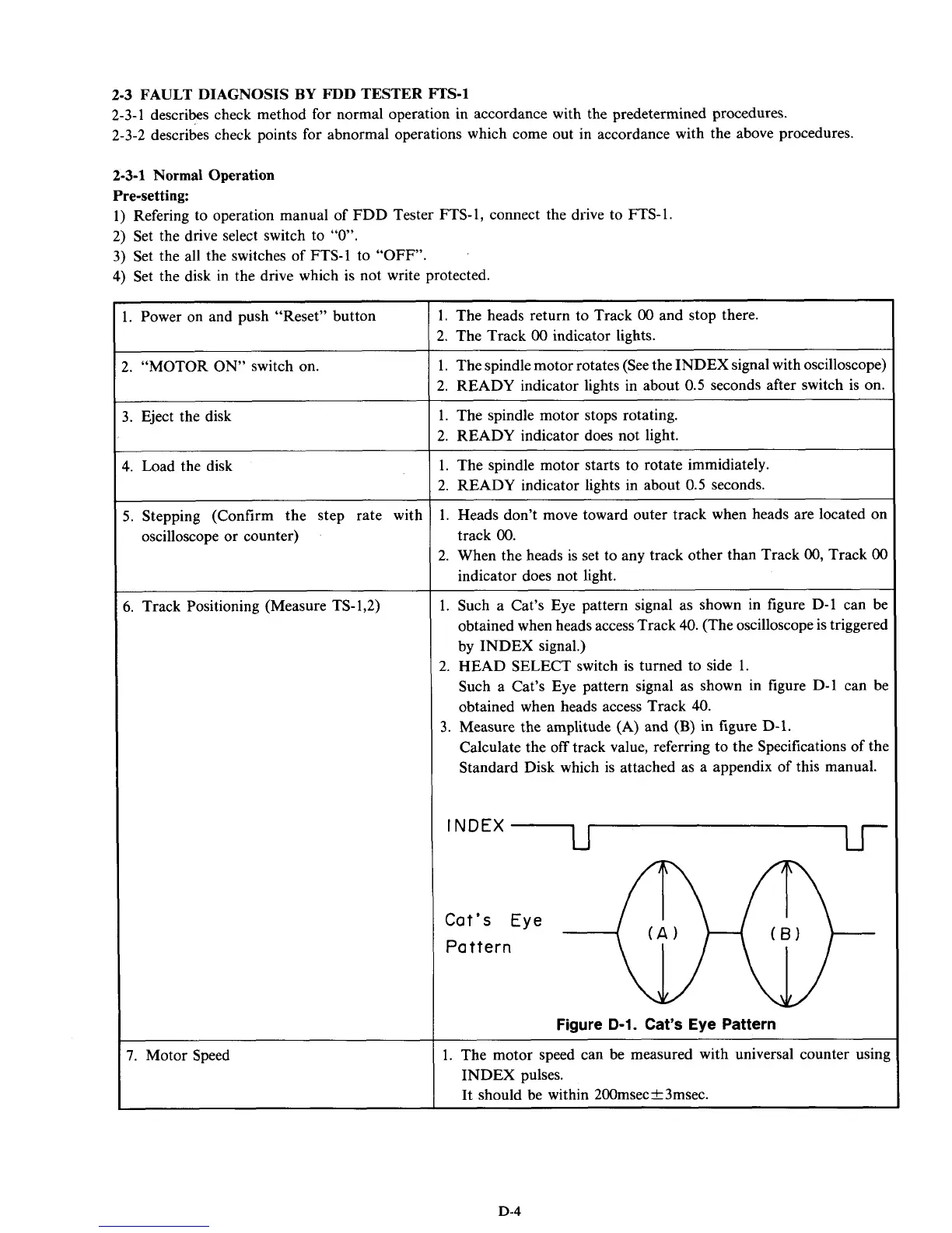
1. Such a Cat’s Eye pattern signal as shown in figure D-1 can be
obtained when heads access Track
40.
(The oscilloscope is triggered
by INDEX signal.)
2.
HEAD SELECT switch is turned to side 1.
Such a Cat’s Eye pattern signal as shown in figure D-1 can be
obtained when heads access Track
40.
Calculate the
off
track value, referring to the Specifications
of
the
Standard Disk which is attached as a appendix of this manual.
3.
Measure the amplitude (A) and
(B)
in figure D-1.
INDEX
~
Figure
D-1.
Cat’s Eye Pattern
1. The motor speed can be measured with universal counter using
INDEX pulses.
It should be within 200msec&3msec.
D-4