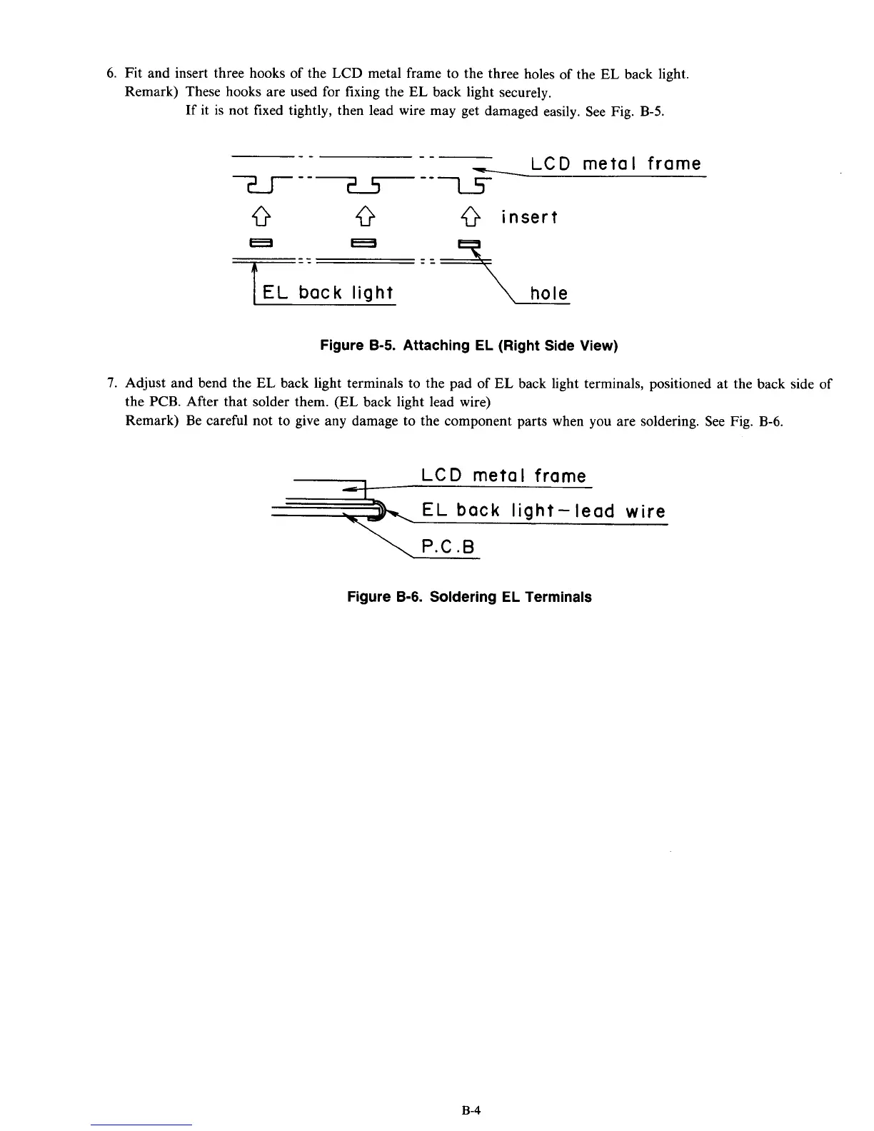
6.
Fit and insert three hooks
of
the
LCD
metal frame to the three holes
of
the
EL
back light.
Remark) These hooks are used for fixing the
EL
back light securely.
If it is not fixed tightly, then lead wire may get damaged easily. See Fig.
B-5.
-- --
-LCD
metal frame
7-J-
---
--l5-
0
insert
.
E
EL
back
light
Figure
8-5.
Attaching EL (Right Side View)
7.
Adjust and bend the
EL
back light terminals to the pad
of
EL
back light terminals, positioned at the back side of
the PCB. After that solder them.
(EL
back light lead wire)
Remark) Be careful not to give any damage to the component parts when you are soldering. See Fig.
B-6.
EL
back
light-lead wire
\
P.C.B
Figure
B-6.
Soldering EL Terminals
B-4