IV-18.
RTC
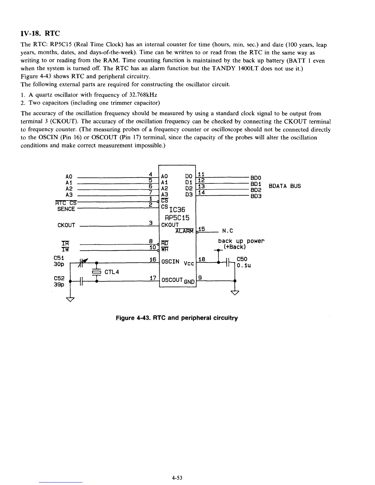
The RTC: RP5C15 (Real Time Clock) has an internal counter for time (hours, min, sec.) and date (100 years, leap
years, months, dates, and days-of-the-week). Time can be written to or read from the RTC in the same way as
writing to or reading from the RAM. Time counting function is maintained by the back up battery (BATT
1
even
when the system is turned
off.
The RTC has an alarm function but the TANDY 1400LT does not use it.)
Figure 4-43 shows RTC and peripheral circuitry.
The following external parts are required for constructing the oscillator circuit.
1. A quartz oscillator with frequency of 32.768kHz
2.
Two capacitors (including one trimmer capacitor)
The accuracy of the oscillation frequency should be measured by using a standard clock signal to be output from
terminal
3
(CKOUT). The accuracy of the oscillation frequency can be checked by connecting the CKOUT terminal
to frequency counter. (The measuring probes of a frequency counter or oscilloscope should not be connected directly
to the OSCIN (Pin 16) or OSCOUT (Pin 17) terminal, since the capacity of the probes will alter the oscillation
conditions and make correct measurement impossible.)
A2
A3
’
m
2
SENCE
CKOUT
A2
D2
-A3
D3
rm
cs
IC36
RP5C
15
CKOUT
m
BDO
BD1
BDATA BUS
BD2
BD3
11
12
13
14
15
N.C
back
up
power
t
(+€lack)
Figure
4-43.
RTC
and
peripheral circuitry
4-53