IV-15. Printer Interface
Figure
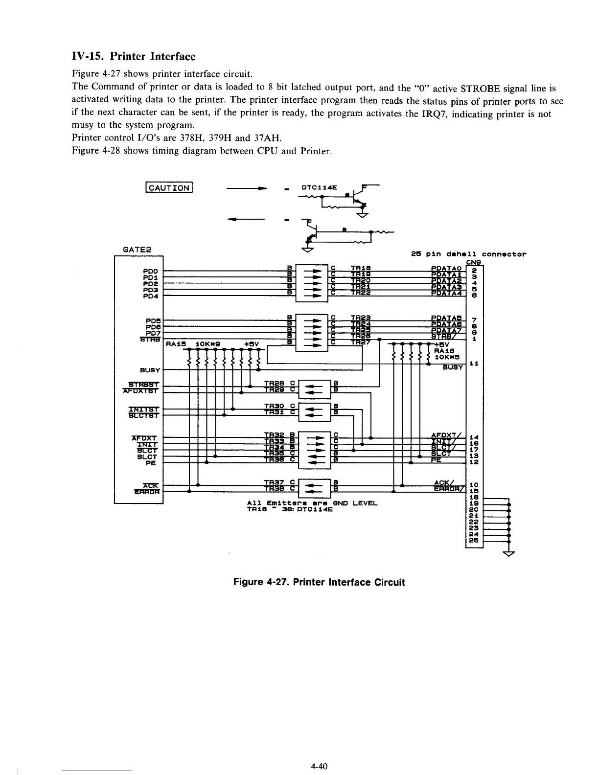
4-27
shows printer interface circuit.
The Command of printer or data is loaded to
8
bit latched output port, and the
‘‘0”
active STROBE signal line is
activated writing data to the printer. The printer interface program then reads the status pins of printer ports to see
if
the next character can be sent,
if
the printer is ready, the program activates the IRQ7, indicating printer is not
musy to the system program.
Printer control
I/O’s
are 378H, 379H and 37AH.
Figure
4-28
shows timing diagram between CPU and Printer.
LCAUTION
I
GATE2
25 pin
dohell
connector
*
PDO
PDI
PO5
PD4
PO2
t
’I
-
u
I
I
PD5
7
PDB
8
PD7
S
HTRB
1
11
BUSY
BTHEsrr
m=lxrmT
TRn?3T
BlIcTBT
14
10
17
13
PE
12
XFaXT
rn
s[IFT
sLcr
I
I
II I
I1
4
1
I5
ACK’
ERRUH.
16
All
Emitterm
are
QND
LEVEL
1B
fRI8
38:
DTC114E 20
21
22
23
24
26
-
Figure
4-27.
Printer Interface Circuit
4-40