IV-10.
I/O
Address
Map
ADDRESS BIT CONTENTS CONTROL
DMA CONTROLLER
08H
09H
OAH
OBH
OCH
ODH
OEH
OFH
INTERRUPT CONTROLLER
020H
021H
TIMERKOUNTER
040H
041H
042H
KEY BOARD/SENSE/CONTROL
060H
0
1
2
3
4
5
6
7
0
061H
062H
REAL TIME CLOCK
070H
07FH
I
1
2
3
4
5
6
7
0
1
2
3
4
5
6
7
37 Command Register
37 Request Register
37 Mask Register
37 Mode Register
37 Clear First/Last
FF
37 Temp Reg/Master clear
37 Clear Mask Register
37 All Mask Register
59
Register
59 Register
53 Counter
0
53 Counter
1
53 Counter 2
PORT
Keyboard Bit
0
Keyboard Bit 1
Keyboard Bit 2
Keyboard Bit 3
Keyboard Bit 4
Keyboard Bit
5
Keyboard Bit 6
Keyboard Bit 7
Gate A Timer Chip for Speaker Tone
output
Enable Speaker
Open for other uses
Read High switches or Read Low switches.
Open for other uses
Open for other uses
Keyboard buffering SW.
Keyboard interrupt reset
System status of hardware
System status
of
hardware
System status of hardware
System status of hardware
Open for other uses
To test Timer output
I/O
channel check (always
low
level)
RAM parity check (always low level)
Real Time Clock Register
Command
&
Status
Write only
Write only
Write only
Write only
R
=
Temp Register
Write only
Write only
IRR
&
ISR
IMR
Interrupt Request
0
For DRAM Refresh
Beep
Port
A
Port B
Port C
-
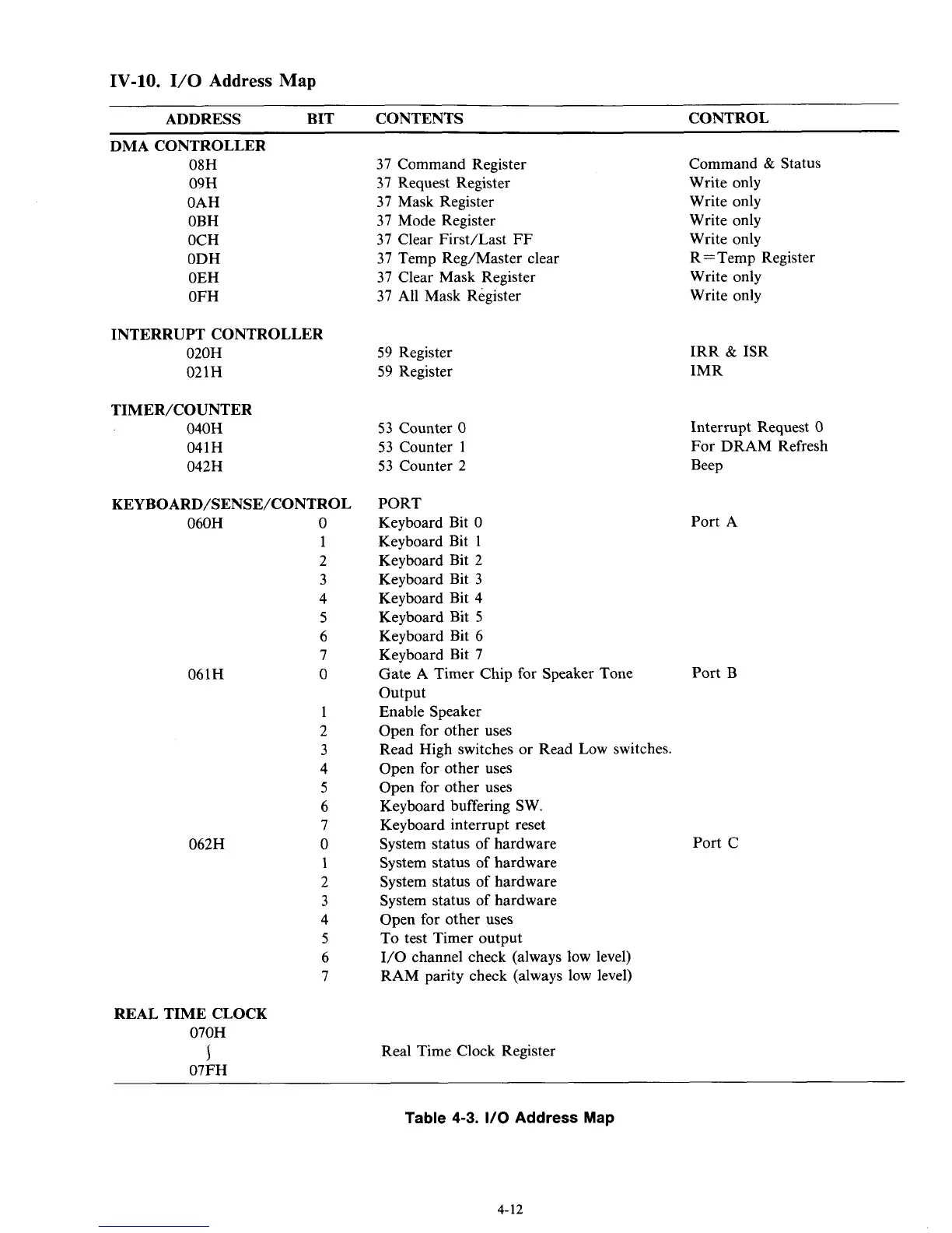
Table
4-3.
I/O
Address Map
4-12