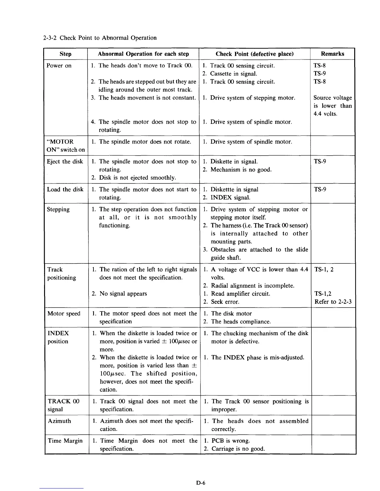
2-3-2
Check Point to Abnormal Operation
Step
Power on
“MOTOR
ON” switch on
Eject the disk
Load the disk
Stepping
Track
positioning
Motor speed
INDEX
position
TRACK
00
signal
Azimuth
Time Margin
Abnormal Operation for each step
1. The heads don’t move to Track
00.
2.
The heads are stepped out but they are
idling around the outer most track.
3.
The heads movement is not constant.
4.
The spindle motor does not stop to
rotating.
1. The spindle motor does not rotate.
1.
The spindle motor does not stop to
2. Disk is not ejected smoothly.
1. The spindle motor does not start to
rotating.
rotating.
1. The step operation does not function
at all, or it is not smoothly
functioning.
1. The ration of the left to right signals
does not meet the specification.
2. No signal appears
1. The motor speed does not meet the
specification
1. When the diskette is loaded twice or
more, position is varied
*
100psec or
more.
2. When the diskette is loaded twice or
more, position is varied less than
f
100psec. The shifted position,
however, does not meet the specifi-
cation.
1. Track
00
signal does not meet the
specification.
1. Azimuth does not meet the specifi-
cation.
1. Time Margin does not meet the
specification.
Check
Point
(defective place)
1.
Track
00
sensing circuit.
2.
Cassette in signal.
1.
Track
00
sensing circuit.
1.
Drive system of stepping motor
I.
Drive system of spindle motor.
1. Drive system of spindle motor.
1. Diskette in signal.
2.
Mechanism is no good.
1. Diskettte in signal
2.
INDEX signal.
1.
Drive system
of
stepping motor
or
stepping motor itself.
2.
The harness (i.e. The Track
00
sensor)
is internally attached to other
mounting parts.
3.
Obstacles are attached to the slide
guide shaft.
1.
A voltage of VCC is lower than
4.4
2.
Radial alignment is incomplete.
1.
Read amplifier circuit.
2. Seek error.
volts.
1.
The disk motor
2. The heads compliance.
~ ~
1.
The chucking mechanism of the disk
motor is defective.
1. The INDEX phase is mis-adjusted.
1.
The Track
00
sensor positioning ic
improper.
1.
The heads does not assemblec
correctly.
1.
PCB is wrong.
2.
Carriage is no good.
Remarks
rs-s
rs-9
rs-s
Source voltage
is
lower than
1.4
volts.
TS-9
TS-9
TS-I, 2
TS-1,2
Refer to 2-2-3
D-6