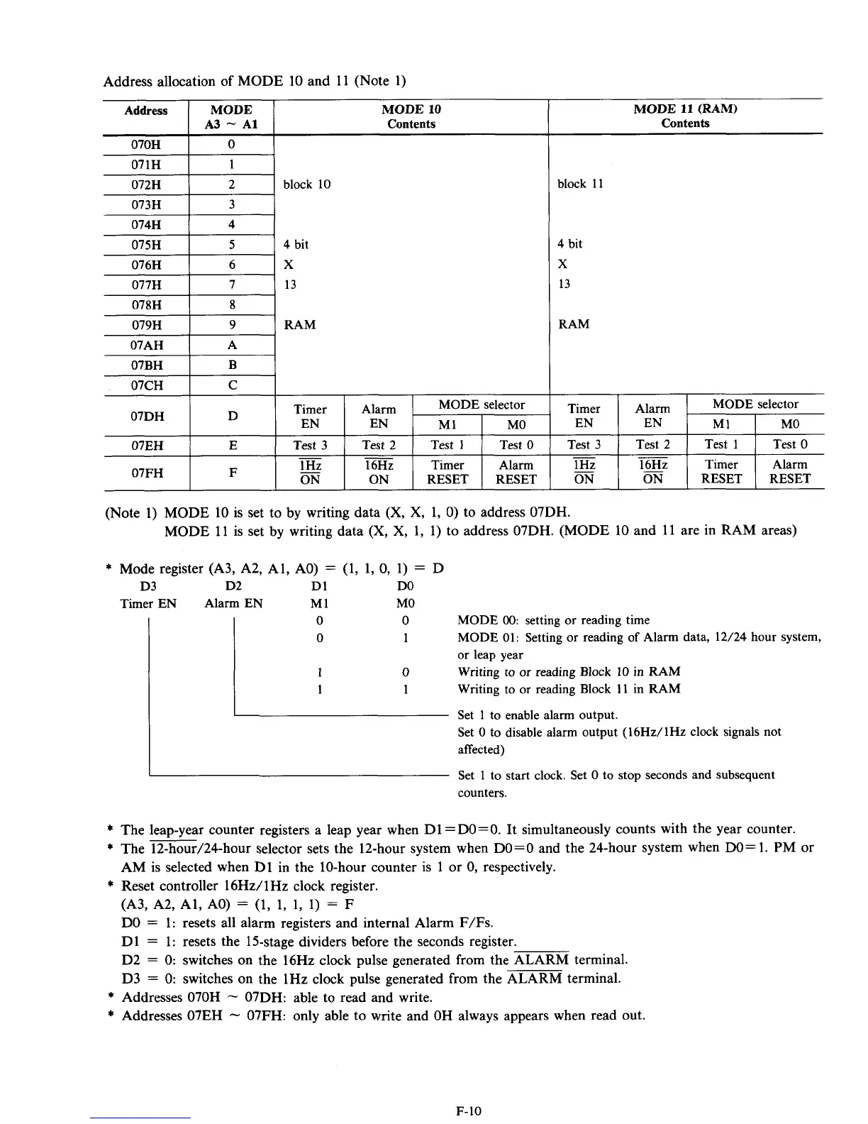
Address allocation
of
MODE 10 and 11 (Note 1)
Address
070H
MODE MODE
10
A3
-
A1
Contents
0
071H
I
1
I
075H
I
5
I
4
bit
079H
I
9
I
RAM
I I
I
I
I
07EH
I
E
1
Test 3
I
Test
2
1
Test
1
1
Test
0
-
-
1
Hz
16Hz Timer Alarm
ON
ON RESET RESET
-
07FH F
MODE 11 (RAM)
Contents
block
11
4
bit
X
13
RAM
MODE selector
Timer
I
Aiim
1
M1
,
MO
EN
Test 3 Test
0
(Note 1) MODE 10 is set to by writing data
(X,
X,
1,
0)
to address 07DH.
MODE 11 is set by writing data
(X,
X,
1, 1) to address 07DH. (MODE 10 and 11 are in RAM areas)
*
Mode register (A3, A2, Al, AO)
=
(1, 1,
0,
1)
=
D
D3 D2 D1
DO
Timer EN Alarm EN M1
MO
MODE
00:
setting or reading time
MODE
01:
Setting
or reading
of
Alarm data, 12/24
hour
system,
or leap year
Writing to or reading Block
10
in
RAM
Writing to or reading Block 11
in
RAM
Set
1
to enable alarm output.
Set
0
to disable alarm output (16Hz/lHz clock signals not
affected)
I
Set 1
to
start clock. Set
0
to stop seconds
and
subsequent
counters.
*
The leap-year counter registers a leap year when D1 =DO=O. It simultaneously counts with the year counter.
*
The 12-hour/24-hour selector sets the 12-hour system when
DO=O
and the 24-hour system when DO=l. PM or
AM is selected when D1 in the 10-hour counter is 1 or
0,
respectively.
*
Reset controller 16Hz/lHz clock register.
(A3, A2, Al, AO)
=
(1, 1, 1, 1)
=
F
DO
=
1: resets all alarm registers and internal Alarm F/Fs.
D1
=
1: resets the 15-stage dividers before the seconds register.
D2
=
0:
switches on the 16Hz clock pulse generated from the ALARM terminal.
D3
=
0:
switches on the 1Hz clock pulse generated from the ALARM terminal.
*
Addresses 070H
-
07DH: able to read and write.
*
Addresses 07EH
-
07FH: only able to write and OH always appears when read out.
F-10