Bit
0
This bit, when set, enables the Sprite Blinking. Blinking period is
16
frame interval. This bit, when reset,
will disable the blinking.
This bit, when set, enables the Sprite
1
function.
This bit, when set, enables the Sprite
2
function.
These three bits define the offset value. The screen raster will be shifted this number upward in the text
mode.
These bits select the Test Mode
of
this controller. These bits can’t be used and should be kept zero.
These bits, if set, enable the operation and can’t be used normally. These bits are cleared by the Vertical
Sync signal.
Bit
1
Bit
2
Bit
3-5
Bit
6,7
This register is cleared by the RESET signal.
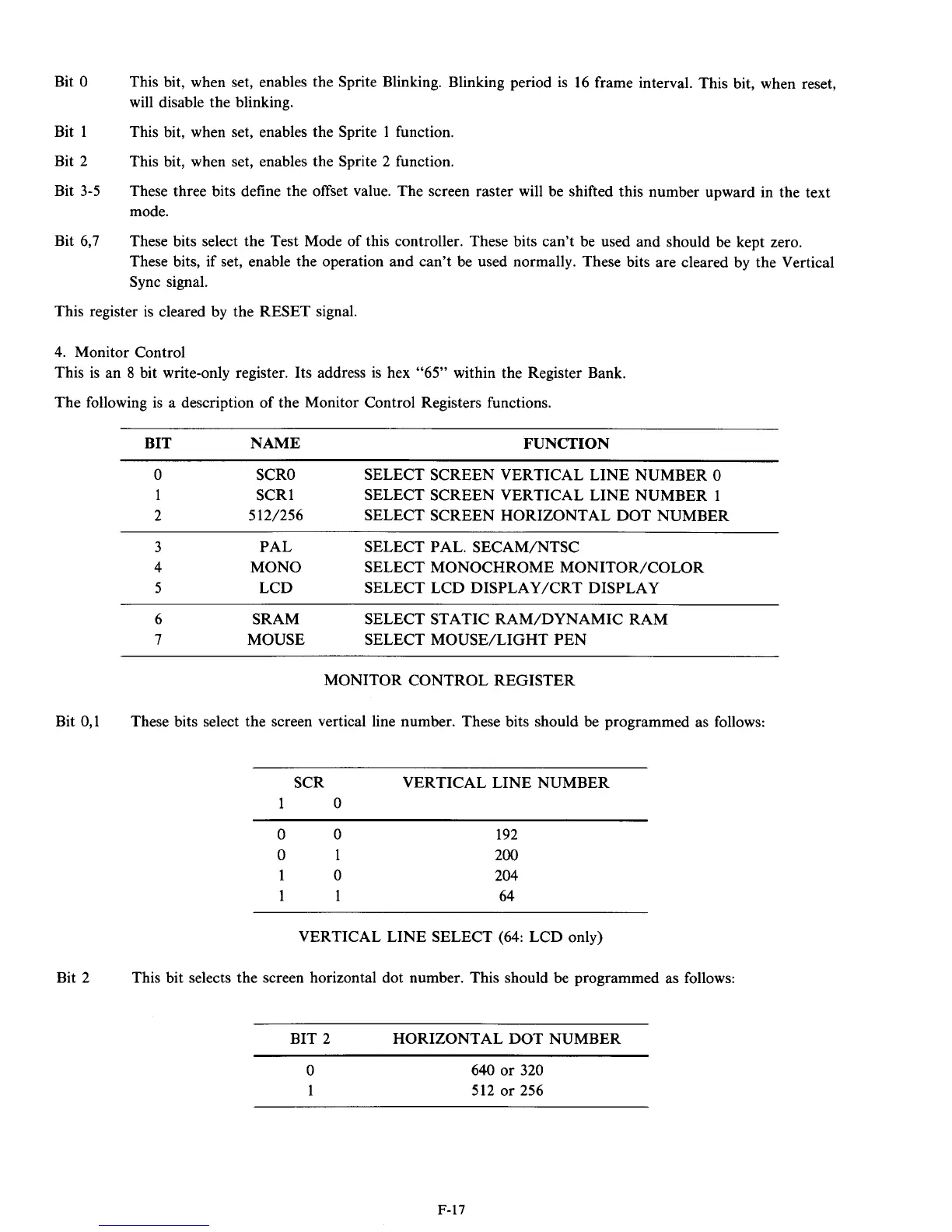
4.
Monitor Control
This is an
8
bit write-only register. Its address is hex
“65”
within the Register Bank.
The following is a description of the Monitor Control Registers functions.
Bit
0,l
Bit
2
BIT NAME FUNCTION
0
SCRO
SELECT SCREEN VERTICAL LINE NUMBER
0
1
SCR
1
SELECT SCREEN VERTICAL LINE NUMBER
1
2
5
12/256
SELECT SCREEN HORIZONTAL DOT NUMBER
3
PAL SELECT PAL. SECAM/NTSC
4
MONO SELECT MONOCHROME MONITOR/COLOR
5
LCD
SELECT LCD DISPLAYKRT DISPLAY
6
SRAM
SELECT STATIC RAM/DYNAMIC RAM
7
MOUSE
SELECT MOUSE/LIGHT PEN
MONITOR CONTROL REGISTER
These bits select the screen vertical line number. These bits should be programmed as follows:
SCR VERTICAL LINE NUMBER
1
0
0
0
0
1
1
0
1 1
192
200
204
64
VERTICAL LINE SELECT
(64:
LCD only)
This bit selects the screen horizontal dot number. This should be programmed as follows:
BIT
2
HORIZONTAL DOT NUMBER
0
1
640
or
320
512
or
256
F-17