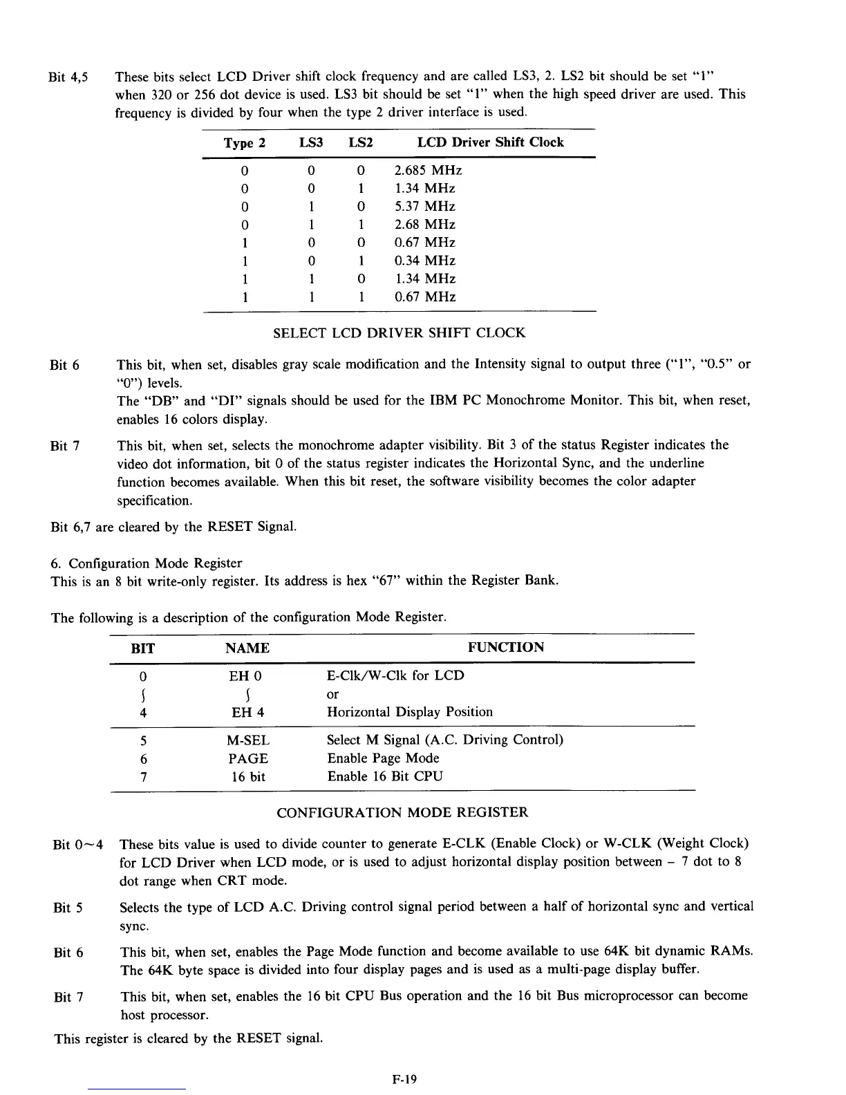
Bit
4,5
These bits select LCD Driver shift clock frequency and are called
LS3, 2.
LS2
bit should be set
“1”
when
320
or
256
dot device is used.
LS3
bit should be set
“1”
when the high speed driver are used. This
frequency is divided by four when the type
2
driver interface is used.
Type
2 LS3 LS2 LCD
Driver Shift
Clock
0
2.685
MHz
1
1.34
MHz
0
5.37
MHz
1
2.68
MHz
0
0.67
MHz
1
0.34
MHz
0
1.34
MHz
1
0.67
MHz
SELECT LCD DRIVER SHIFT CLOCK
Bit
6
This bit, when set, disables gray scale modification and the Intensity signal to output three
(“I”,
“0.5”
or
“0”)
levels.
The “DB” and “DI” signals should be used for the IBM PC Monochrome Monitor. This bit, when reset,
enables
16
colors display.
This bit, when set, selects the monochrome adapter visibility. Bit
3
of the status Register indicates the
video dot information, bit
0
of the status register indicates the Horizontal Sync, and the underline
function becomes available. When this bit reset, the software visibility becomes the color adapter
specification.
Bit
7
Bit
6,7
are cleared by the RESET Signal.
6.
Configuration Mode Register
This is an
8
bit write-only register. Its address is hex
“67”
within the Register Bank.
The following is a description of the configuration Mode Register.
BIT NAME FUNCTION
0
EH
0
E-CIk/W-CIk for LCD
4
EH
4
or
Horizontal Display Position
I I
5
M-SEL Select M Signal (A.C. Driving Control)
6
PAGE Enable Page Mode
7 16
bit Enable
16
Bit CPU
CONFIGURATION MODE REGISTER
Bit
0-4
These bits value is used to divide counter to generate E-CLK (Enable Clock) or W-CLK (Weight Clock)
for LCD Driver when LCD mode, or is used to adjust horizontal display position between
-
7
dot to
8
dot range when CRT mode.
Selects the type of LCD A.C. Driving control signal period between a half of horizontal sync and vertical
sync.
This bit, when set, enables the Page Mode function and become available to use
64K
bit dynamic RAMS.
The
64K
byte space is divided into four display pages and is used as a multi-page display buffer.
This bit, when set, enables the
16
bit CPU Bus operation and the
16
bit Bus microprocessor can become
host processor.
Bit
5
Bit
6
Bit
7
This register is cleared by the RESET signal.
F-19