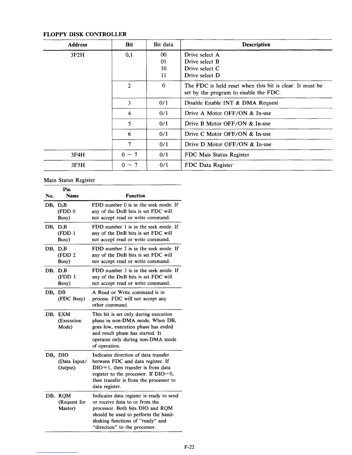
FLOPPY DISK CONTROLLER
~
3F2H
091
00
01
10
11
2
0
3
o/
1
4
O/
1
Address
I
Bit
I
Bit data
I
Description
~~
Drive select A
Drive select B
Drive select C
Drive select D
The FDC is held reset when this bit is clear. It must be
set by the program to enable the FDC.
Disable Enable INT
&
DMA Request
Drive A Motor OFF/ON
&
In-use
3F4H
--?
I
0/1
I
Drive B Motor OFF/ON
&
In-use
7
o/
1
Drive D Motor OFF/ON
&
In-use
0-7
o/
1
FDC Mais Status Register
1
6
1
0/1
1
Drive C
Motor
OFF/ON
&
In-use
3F5H
1
0
-
7
1
0/1
1
FDC Data Register
Main Status Register
~~ ~
Pin
No.
Name
Function
DB, D,B
FDD number
0
is in the seek mode. If
any of the DnB bits is set FDC will
not accept read
or
write command.
(FDD
0
BUSY)
DB, DIB
FDD number
1
is in the seek mode. If
any of the DnB bits is set FDC will
not accept read or write command.
(FDD
1
BUSY)
DB, D,B
FDD number 2 is in the seek mode. If
any of the DnB bits is set FDC will
not accept read
or
write command.
(FDD 2
BUSY)
DB, D,B
FDD
number
3
is in the seek mode. If
any of the DnB bits is set FDC will
not accept read
or
write command.
process. FDC will not accept any
other command.
(FDD
3
BUSY)
(FDC Busy)
DB, DB A Read
or
Write command is in
DB, EXM This bit is set only during execution
phase in non-DMA mode. When DB,
goes low, execution phase has ended
and result phase has started. It
operates only during non-DMA mode
of operation.
(Execution
Mode)
DB, DIO Indicates direction of data transfer
(Data Input/ between FDC and data register. If
Output) DIO=
1,
then transfer is from data
register to the processor. If DIO=O,
then transfer is from the processor to
data register.
DB, RQM Indicates data register is ready to send
(Request for
Master)
or receive data to
or
from the
processor. Both bits DIO and RQM
should be used to perform the hand-
shaking functions of “ready” and
“direction” to the processor.
F-22