COMl
CONTROL
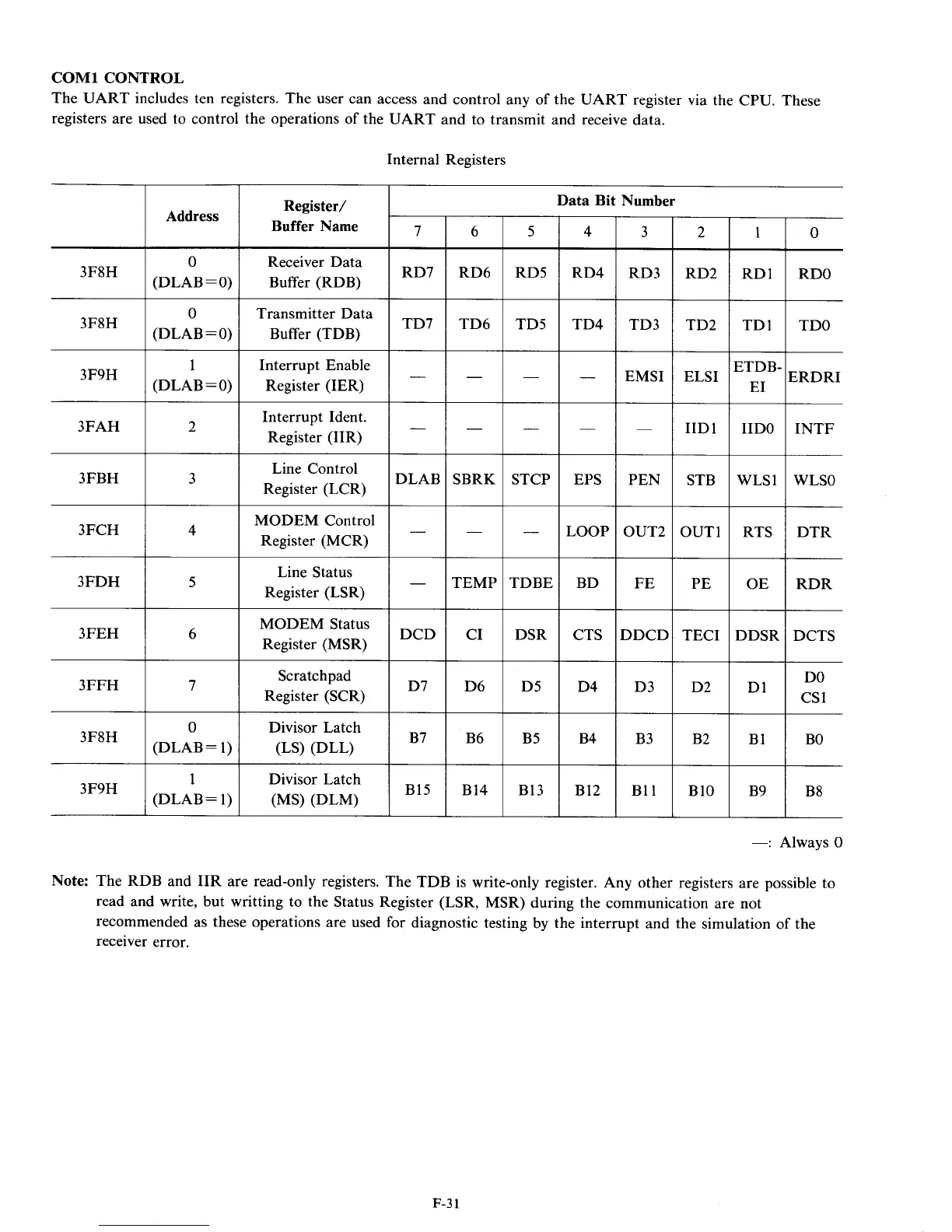
The UART includes ten registers. The user can access and control any of the UART register via the CPU. These
registers are used
to
control the operations of the UART and to transmit and receive data.
3F8H
3F8H
3F9H
3FAH
Internal Registers
Address
0
(DLAB
=0)
0
(DLAB
=0)
1
(DLAB=O)
2
Data Bit Number
2
Register/
Buffer Name
Receiver Data
Buffer (RDB)
1
0
STB
OUT1
PE
TECI
6
WLS1 WLSO
RTS DTR
OE RDR
DDSR DCTS
3
7
RD7
TD7
-
5
RD5
4
RD4
RD3
RD2
1
RDl
I
RDO
RD6
TD6
TD5
TD4
TD3
Transmitter Data
Buffer (TDB)
Interrupt Enable
Register (IER)
EMS1
Interrupt Ident.
Register (IIR)
IID1
I
IIDO
I
INTF
3FBH
1
3
Line Control
Register (LCR)
DLAB
SBRK STCP EPS PEN
MODEM Control
Register (MCR)
LOOP OUT2
Line Status
Register (LSR)
TEMP TDBE
BD
CTS
D4
FE
DDCI:
3FEH
I
6
MODEM Status
Register (MSR)
DCD
D7
B7
CI
D6
DSR
D5
3FFH
I
7
D3
Scratch pad
Register (SCR)
Divisor Latch
(LS) (DW
(MS) (DLM)
Divisor Latch
B6 B5
B4
B3
0
3F8H
1
(DLAB=l)
B15
B14
B13
B12 B11
1
3F9H
1
(DLAB= 1)
-:
Always
0
Note:
The RDB and IIR are read-only registers. The TDB is write-only register. Any other registers are possible to
read and write, but writting to the Status Register (LSR, MSR) during the communication are not
recommended as these operations are used for diagnostic testing by the interrupt and the simulation of the
receiver error.
F-3
1