G10 Hardware Maintenance Guide 7.13.2 13
1
G10 Probe Overview
Rev. 002-140228
G10 HARDWARE COMPONENTS
The following sections highlight the G10 hardware components.
G10 Front View
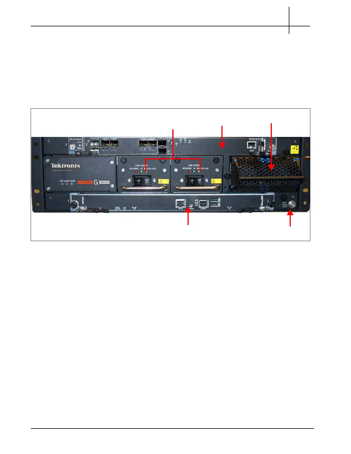
Figure 1.2 shows the front view of the GeoProbe G10.
Figure 1.2 - G10 Probe Front View
The front view of the G10 system provides access to the following hardware components:
Iris Interface Card (IIC200 or IIC100)
Applications Blade (IAP320/IAP200 or IAP100)
Two Power Entry Modules (PEMs) (AC or DC)
Fan Trays (one air inlet fan tray and a second fan tray located on the rear of the G10)
Electro-Static Discharge Points
ESD Bond Point
Power Entry
Modules
Iris Interface Card
(IIC200)
Application Blade
Fan Tray
Tektronix Communications | For Licensed Users | Unauthorized Duplication and Distribution Prohibited

 Loading...