G10 Hardware Maintenance Guide 7.13.2 58
3
Blades and RTMs
Rev. 002-140228
IAP200
IAP200 LEDs
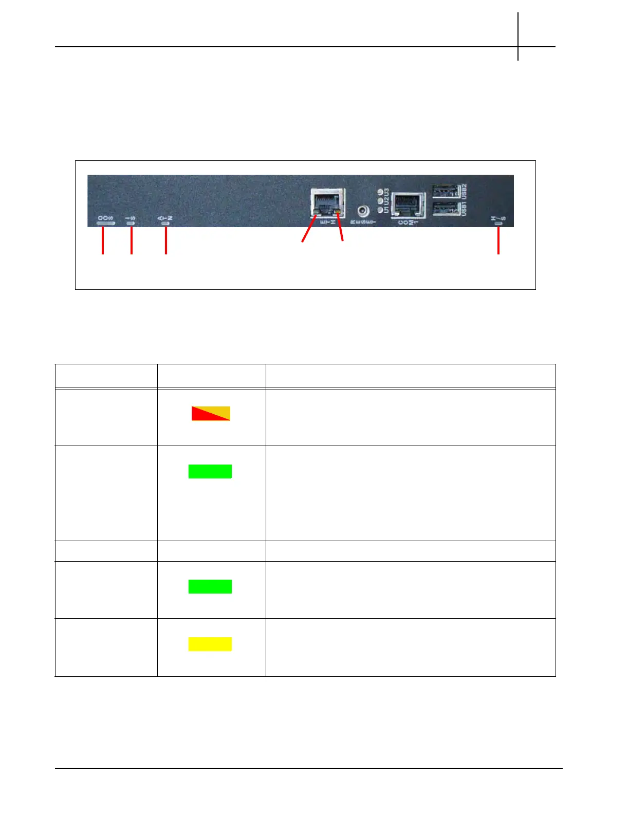
The IAP200 indicators provide status and error information. The LED indicators are located on
the front panel of the board. Figure 3.25 displays the front panel LEDs of the IAP200.
Figure 3.27 - IAP200 Front Panel LEDs
Table 3.16 displays the IAP200 LED indicators.
OOS IS ATN
H/S
ETH
Link
ETH
Activity
Table 3.18 - IAP200 LED Indicators
LED LED Color Description
OOS RED or AMBER Indicates out of service status.
RED or AMBER—The CPM is out of service.
OFF—Normal operation.
IS GREEN Indicates Payload Power status.
GREEN—Payload power has been has been enabled by
the IPMC. Note that this LED indicates the payload
power status both in the early power state and the normal
blade operation.
OFF—Payload power is disabled.
ATN Not Used.
ETH Link LED GREEN
Indicates status of Ethernet connector.
GREEN—The link is available.
OFF—No link established.
ETH Activity LED YELLOW
Indicates the status of Ethernet traffic on the connection.
YELLOW—Ethernet activity occurring.
OFF—No Ethernet activity occurring.
Tektronix Communications | For Licensed Users | Unauthorized Duplication and Distribution Prohibited

 Loading...