G10 Hardware Maintenance Guide 7.13.2 25
2
Chassis Subsystem
Rev. 002-140228
Rear Panel Connectors
Table 2.2 describes the connectors available on the SHmm (Figure 2.2).
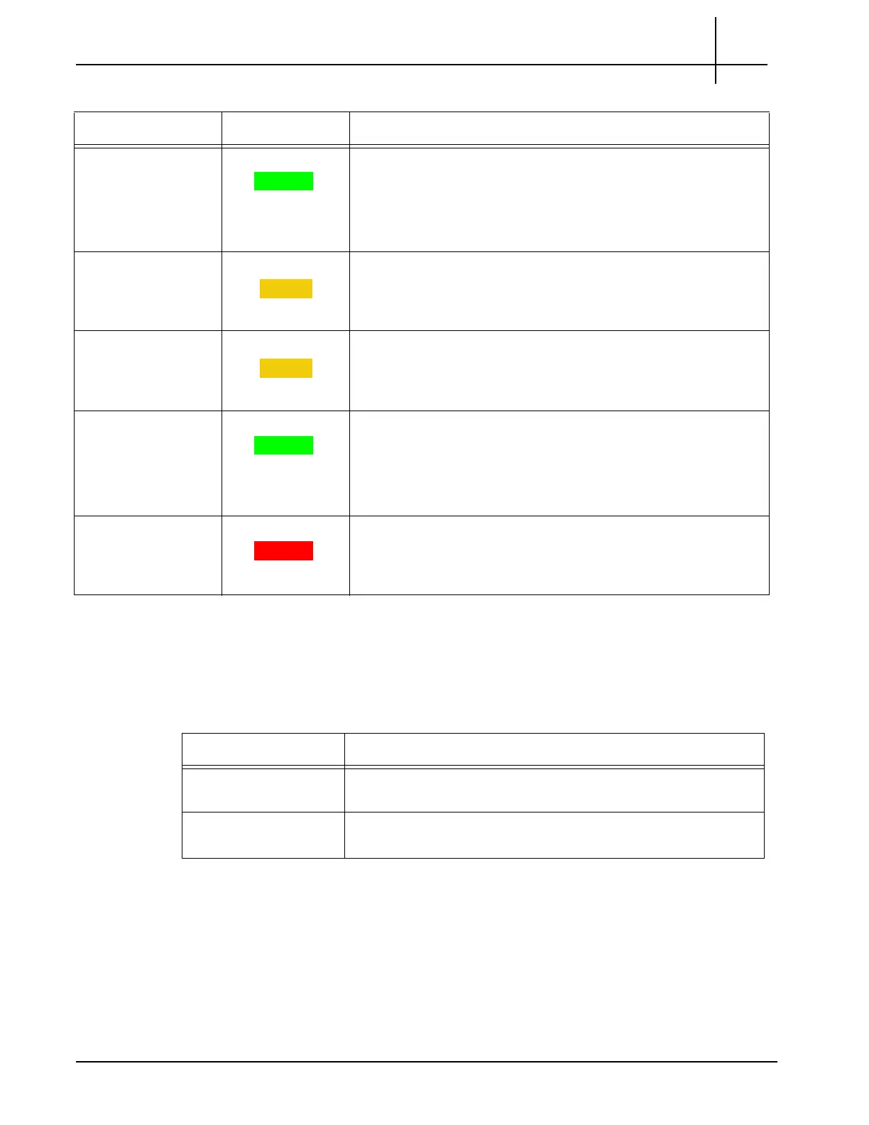
Base Channel 2 GREEN Indicates the Ethernet connection to the chassis 1
G backplane.
GREEN—The link to base channel 2 is available.
BLINKING—Link and activity.
OFF—Otherwise.
Ethernet
Mana
gement
Activity
AMBER Indicates system manager Ethernet link activity.
AMBER—Activity.
OFF—No activity.
ACT MGMT AMBER Indicates which Shmm is active.
AMBER—The SHmm is active.
OFF—The SHmm is in standby mode.
OK GREEN Indicates normal system functions.
GREEN—The Shmm is operating properly.
OFF—Otherwise.
BLINKING—The board boots up.
OOS RED Indicates SHMM failure.
RED—The Shmm is out-of-service.
OFF—The Shmm is operating properly.
Table 2.1 - LED Indicators of the Shmm (Continued)
LED LED Co
lor Description
Table 2.2 - Connectors of the Shmm
LED/Connector Description
Ethernet Management This port provides 10/100 Mb connectivity to the customer LAN
for
Operations, Administration, and Maintenance (OAM).
Ethernet Uplink
Conne
ctor
In some configurations, this is used to connect to the
management port on the disk enclosure.
Tektronix Communications | For Licensed Users | Unauthorized Duplication and Distribution Prohibited

 Loading...