G10 Hardware Maintenance Guide 7.13.2 14
1
G10 Probe Overview
Rev. 002-140228
G10 Rear View
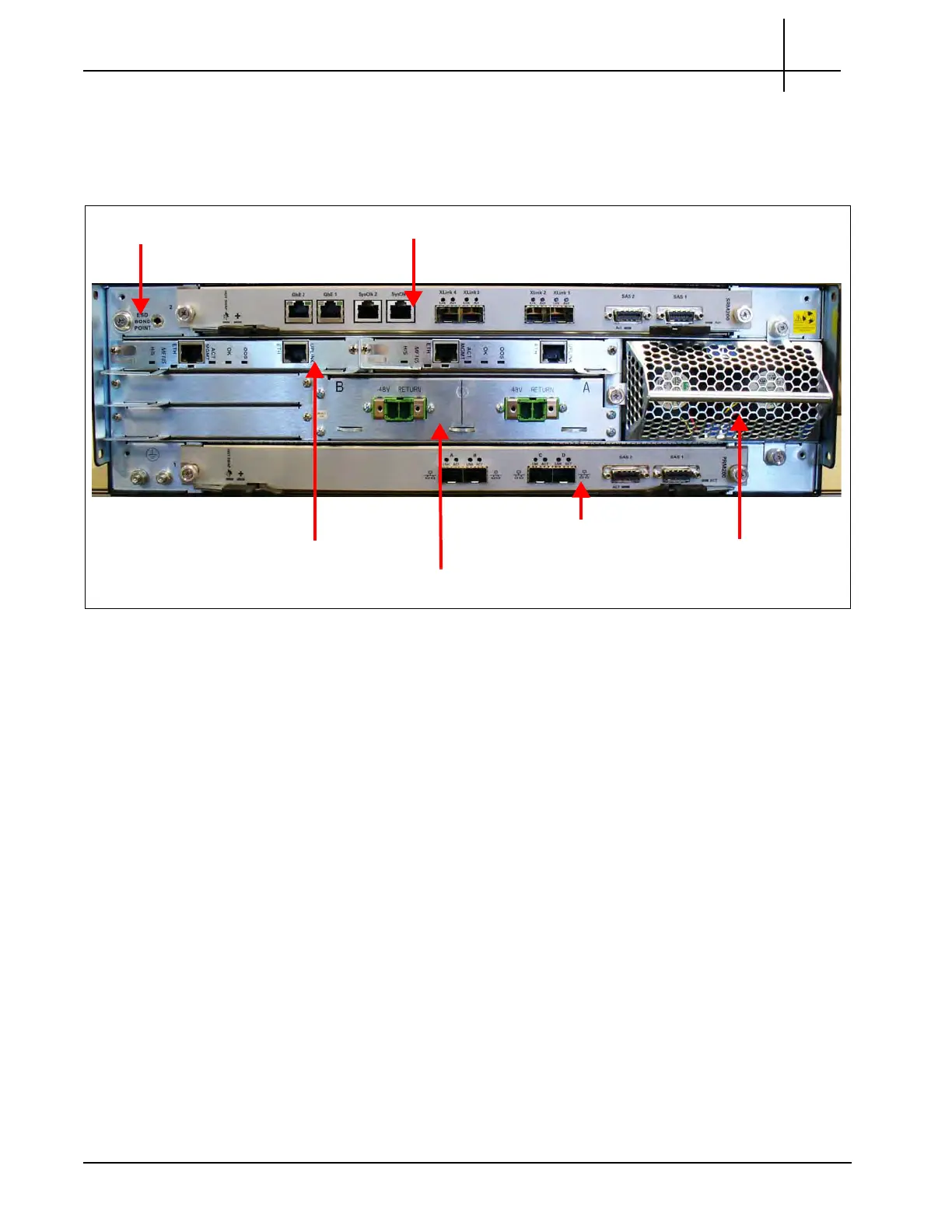
Figure 1.3 shows rear views of the GeoProbe G10. The IIC RTM installed in Slot 2 (top slot)
varies depending on the G10 configuration.
Figure 1.3 - G10 Probe Rear View
The rear view of the GeoProbe G10 system provides access to the following hardware
compone
nts:
Slot 2 (Top)—Installed IIC RTM varies per G10 model:
- 8x1G Model: SRM100 R
TM (Connects to IIC100)
- Mixed 1G and 10G Model: SRM2
00 RTM (connects to IIC200) or TRM100 RTM
(connects to IIC100 or IIC200)
Slot 1 (Bottom)—Applications Blade RTM (PRM300 RTM/PRM200 RTM or PRM100
RTM)
Redundant Shelf Manager (SHmm)
Fan Trays (front to rear air flow)
Rear connection for power cables
Electro-Static Discharge Points
ESD Bond Point
SHmm Shelf Managers
Applications Blade RTM
AC or DC Power Connectors
Fan Tray
SRM200 RTM
Tektronix Communications | For Licensed Users | Unauthorized Duplication and Distribution Prohibited

 Loading...