G10 Hardware Maintenance Guide 7.13.2 49
3
Blades and RTMs
Rev. 002-140228
TRM100 RTM
The TRM100 RTM is used in the following configurations:
Mixed 1G and 10G Ethernet probe installations with IIC100
Mixed 1G and 10G Ethernet probe installations with IIC200 supporting eHRPD
monitoring
The TRM100 RTM connects to the back of the GeoProbe G10 chassis in the upper slot
location
and performs the following functions:
Communicates the board’s health and configuration status to its counterpart IPMC on
the IIC100 or IIC200
Serves as the store-to-disk interface to the disk array with 10Gb Ethernet capability.
Provides four 10G optical inputs for monitored links when used with IIC100. (When
used with IIC200, no 10G monitored links are connected to the TRM100 RTM; all 10G
monitored traffic is connected to the IIC200 [LPC200].
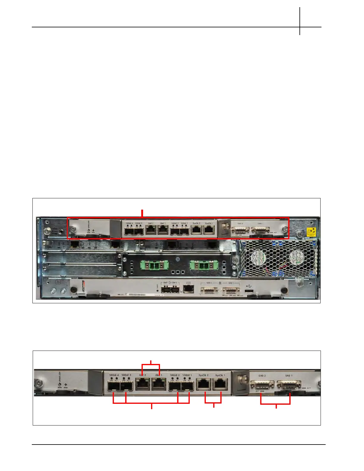
Figure 3.20 displays the TRM100 RTM.
Figure 3.20 - TRM100 RTM
TRM100 RTM Connectors
Figure 3.21 displays the TRM100 RTM connectors.
Figure 3.21 - TRM100 RTM Connectors
10GbE Connectors (4)
Sys Clock
SAS Connectors (2)
GbE Connectors (2)
Tektronix Communications | For Licensed Users | Unauthorized Duplication and Distribution Prohibited

 Loading...