G10 Hardware Maintenance Guide 7.13.2 50
3
Blades and RTMs
Rev. 002-140228
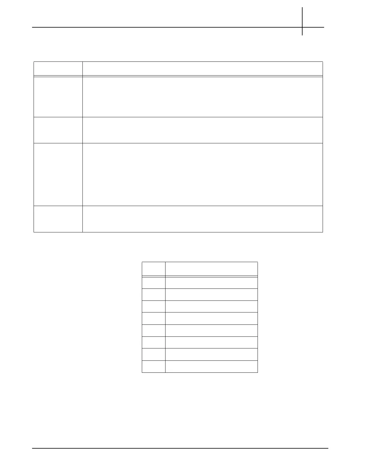
Table 3.11 describes the TRM100 RTM connectors.
Table 3.12 shows the RJ45 pin assignments for the SYSCLK
connectors.
Table 3.11 - TRM100 RTM Connectors
Connector Description
10GbE (4) 10 GbE SFP+ (fiber) connectors
When used with IIC100, these ports provide inputs for monitored links or intercage
communications for multiprobe configurations.
When used with the IIC200, these connectors are not used.
GbE (2) Two Gb Ethernet connections
Provide
s connections to storage controller(s).
SysClk (2) System Clock Connectors.
For standalone G10 configurations, these can be used for external SYS CLK
connections.
For the Media Probe configuration, these ports are used for chassis-to-chassis
timing distribution.
Refer to SysClk Termination Switch for more details.
SAS (2) SAS Connectors
Provides connections to external storage subsystem.
Table 3.12 - SYSCLK RJ45 Pin Assignments
Pin Description
1 CARR_CLK1A+
2 CARR_CLK1A-
3 CARR_CLK2A+
4 no connect
5 no connect
6 CARR_CLK2A-
7 CARR_CLK3A+
8 CARR_CLK3A-
Tektronix Communications | For Licensed Users | Unauthorized Duplication and Distribution Prohibited

 Loading...